5 special i/o modes, Ktlx800/pitx user's guide, 1 irq mode – Kontron KTLX800-pITX User Manual
Page 33: 2 tri-sta, Te mode
KTD-S0022-C
Page 28
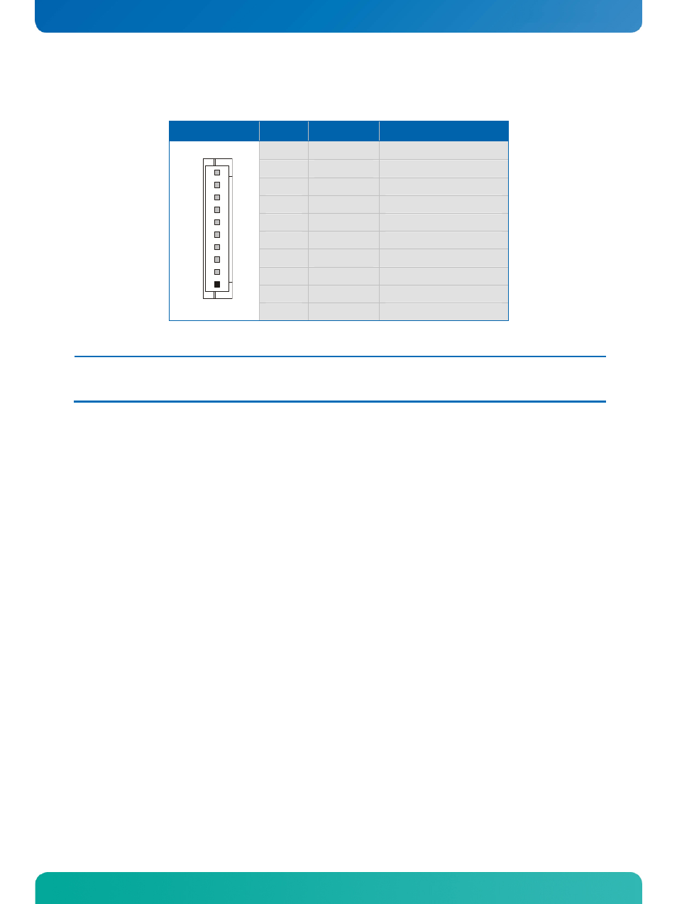
Digital I/O Interface
KTLX800/pITX User's Guide
The digital I/O interface is available through the Molex connector J2 (10 pins). An interface cable (open
is
O-PROTO-10, part number 62038).
ended) deliverable from KONTRON (KAB-GPI
Header
Pin
Signal Name
Function
1
VCC
1)
Power +3.3V
GPIO4
2
Bidirectional I/O 4
3
GPIO0
Bidirectional I/O 0
4
GPIO5
Bidirectional I/O 5
5
GPIO1
Bidirectional I/O 1
6
GPIO6
Bidirectional I/O 6
7
GPIO2
Bidirectional I/O 2
8
GPIO7
Bidirectional I/O 7
9
GPIO3
Bidirectional I/O 3
1
10
GND
Ground
Note:
1)
To protect the external power lines of peripheral devi
ake sure that
- the wires have the right diameter to withstand the maximum available current.
- to enclosure of the peripheral device fulfills the fire-protecting conditions of IEC/EN 60950.
ces m
13.5 Special I/O Modes
13.5.1 IRQ
Mode
All
edge of the signal.
However for th
lines are used. If
more IRQ pins shou
the input pins.
13.5.2 Tri-Sta
tri-state mode the pins are automatically configured as output pins. In contrast to a standard ouput pin
the tri-state pin can also be used as an input pin (i.e. acknowledge from I2C-Bus).
sixteen I/O lines can be configured to trigger an interrupt on the falling or rising
e interrupt handling only IRQ6 and IRQ7 are available even when more
ld be used the identification of the source must be done by sampling
te
Mode
In