Italiano english – FBT FORMULA 248 User Manual
Page 10
SEZIONE MASTER
MASTER SECTION
ITALIANO
ENGLISH
8
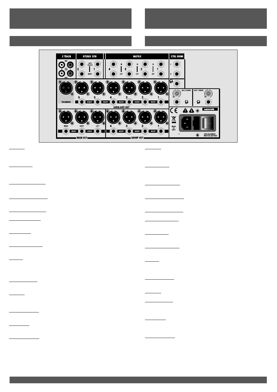
2 TRACK
STEREO RTN
AUXILIARYOUT 1 - 6
INSERT ( auxiliary out)
MAINOUTL/R-MONO
INSERT (main out)
GROUPOUT
MATRIX
CTRLROOM L/R
PHONES
AUX 1/2 HEADPH
TALKBACK
ALIMENTAZIONE
Prese CINCH RCA per la connessione di un registratore a 2 tracce (es. DAT
recorder). Collegare gli ingressi di un apparato di registrazione alle prese
SND e le uscite alle preseRTN.
Prese jack da usare come ingressi stereo ausiliari; collegando solo il jack
LEFT (mono) il mixer riconoscerà il segnale come mono e diffonderà lo
stesso segnale ad entrambi i jack L e R.
Prese XLR in cui sono presenti i segnali degli Ausiliari 1-6 provenienti dai
controlli generali AUX 1-6 ( vedi descrizione dei comandi
Prese jack stereo di ingresso-uscita per collegare apparecchiature esterne
sulle uscite AUXILIARY.
Prese XLR incui sono presenti i segnali delMAIN L/R e MONO.
Prese jack stereo di ingresso/uscita per collegare apparecchiature esterne
(equalizzatori, ecc..) sulle usciteMain.
prese jack stereo bilanciate in cui sono presenti i segnali della Matrice
(1/2/3/4)
prese jack stereo bilanciate per collegare il segnale mono da sommare
allaMatrice (1/2/3/4).
L’uscita Control Room viene normalmente collegata con il sistema monitor
della regia.
Presa jack stereo per collegare una cuffia. Prima di collegare la cuffia alla
presa iniziate sempre con il livello Phones azzerato, quindi alzatelo
gradualmente.
Uscite cuffia con relativo volume dei segnali AUX 1 e AUX 2; normalmente
usate per fornire un monitoraggio in cuffia a duemusicisti.
L’ingresso TALKBACK permette di collegare un microfono il cui segnale può
essere inviato alleuscite AUX 1/6, aiGruppi 1/4, alle uscite L/R e MONO.
Interruttore di accensione del mixer: l’accensione è visualizzata dal led PWR
( sul pannello frontale).
Presa per il collegamento alla rete elettrica : 90-240Vac/50-60Hz
Alloggio del fusibile di protezione del circuito di alimentazione: in caso di
rottura del fusibile , quest’ultimo va sostituito solo con fusibili equivalenti:
T2A/250V.
pag.10
).
Prese XLR che forniscono la miscelazione dei segnali controllati dai Fader
GROUP 1/2/3/4.
Prese jack stereo di ingresso/uscita per collegare apparecchiature esterne
(equalizzatori, ecc..) sulle uscite GROUP.
INSERT (groupout)
OUT:
IN:
2 TRACK
STEREO RTN
AUXILIARYOUT1-6
INSERT (auxiliary out)
MAINOUTL/R-MONO
INSERT (main out)
AUX 1/2 HEADP
TALKBACK
POWER SUPPLY
CINCH RCA sockets to connect a 2 tracks recorder (example DAT
recorder). Connects the inputs of a recording equipment to the SND
sockets and the outputs to the RTN sockets.
Jack sockets to be used as auxiliary stereo inputs. If only the LEFT (mono)
jack is connected, the mixer will recognize the signal as mono and route
the same signal to both L and R jacks.
XLR sockets transmitting the signals of the Auxiliaries 1-6 coming from
AUX 1-6maincontrols (see controls description, page 10).
Input-output stereo jack sockets for the connection of external devices to
the AUXILIARY outputs.
XLR sockets on which are present the signals fromMAINL/RandMONO
Headphone outputs with the relevant volume of the AUX 1 and AUX 2
signals. Generally, they are used to provide headphone monitoring to two
musicians.
The TALKBACK input enables the connection of a microphone whose
signal can be routed to the AUX 1/6 outputs , to the Groups 1/4, and to the
L/R and MONO outputs.
Switch to turn on the mixer: the PWR led (on the front panel) lighting on
indicates that the mixer is turned on.
Socket for connection to the mainssupply : 90-240Vac/50-60Hz
Protection fuse housing of the power supply circuit : in case of fuse
breakage, it has to be replaced only withequivalent fuses. T2A/250V.
Input/output stereo jack sockets to connect external equipment
(equalizers, etc.) on the Main outputs.
XLR sockets providing the mixing of the signals controlled by the GROUP
1/2/3/4 Faders.
Input/output stereo jack sockets for the connection of external devices
(equalizers, etc…) to the GROUP outputs.
balanced stereo jack sockets transmittingMatrix (1/2/3/4) signals.
balanced stereo jack sockets for the connection of the mono signal
to be summed to the Matrix (1/2/3/4).
The Control Room output is usually connected with the monitor system of
the control room.
Stereo jack sockets to connect a headphone.
GROUP OUT
INSERT (group out)
MATRIX
CTRLROOML/R
PHONES
OUT:
IN:
90-240V
50-60 Hz
T 2 A - 2 5 0 V
80VA
CAUTION
RISKOFELECTRICSHOCK
DONOTOPEN
0
-6
0
-6