Installing system board options, Kdswhu, Qvwdoolqj6\vwhp%rdug2swlrqv – Dell OptiPlex E1 User Manual
Page 91
Installing System Board Options
6-1
& + $ 3 7 ( 5
,QVWDOOLQJ6\VWHP%RDUG2SWLRQV
This chapter describes how to install the following options:
Peripheral Component Interconnect (PCI) and Industry-Standard Architecture
(ISA) expansion cards
System memory
Video memory
This chapter also includes instructions for replacing the system battery, if necessary.
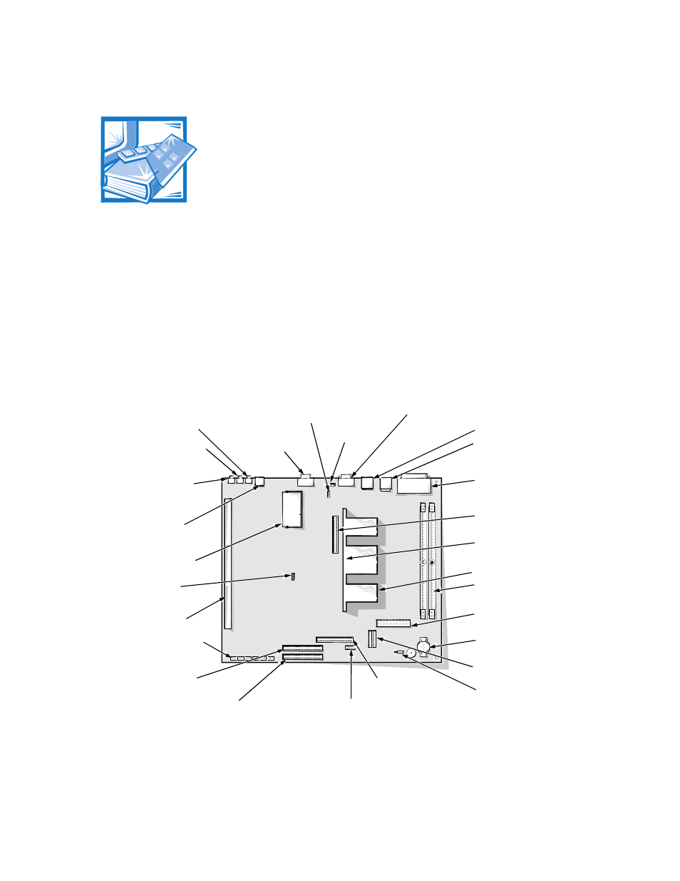
Use Figure 6-1 to locate the system board features.
)LJXUH 6\VWHP %RDUG )HDWXUHV
microprocessor
connector (SLOT1)
microprocessor
fan connector
(FAN)
video connector
(MONITOR)
serial port 2
connector
(SERIAL2)
USB connectors (USB) (2)
parallel/serial port 1
connectors (stacked)
(PARALLEL/SERIAL1)
mouse/keyboard
connectors (stacked)
(MOUSE/KYBD)
video-memory
upgrade socket
(VIDEO_UPGRADE)
control panel
connector (PANEL)
battery socket
(BATTERY)
integrated NIC
connector (ENET)
riser board
connector (RISER)
system board jumpers
primary EIDE interface
connector (IDE1) (pin-1 corner)
secondary EIDE
interface connector
(IDE2) (pin-1 corner)
diskette/tape drive
interface connector
(DSKT) (pin-1 corner)
DIMM sockets (2)
(DIMM_B–DIMM_C)
main power input
connector (POWER_1)
3.3-V power input
connector (POWER_2)
ATI multimedia channel
connector (AMC)
CD-in connector (CD-IN)
chassis intrusion switch
connector (INTRUSION)
heat sink
line-in jack (LINE-IN)
(optional)
line-out jack (LINE-OUT)
(optional)
microphone jack
(MIC) (optional)
telephony
connector (MODEM)
front of
computer