Connecting drives, Connecting drives -4, Figure 7-4 – Dell OptiPlex E1 User Manual
Page 108: Dc power cable connector -4, Figure 7-5, Drive interface connectors -4, Rqqhfwlqj'ulyhv
7-4
Dell OptiPlex E1 Mini Tower Managed PC Reference and Installation Guide
&RQQHFWLQJ'ULYHV
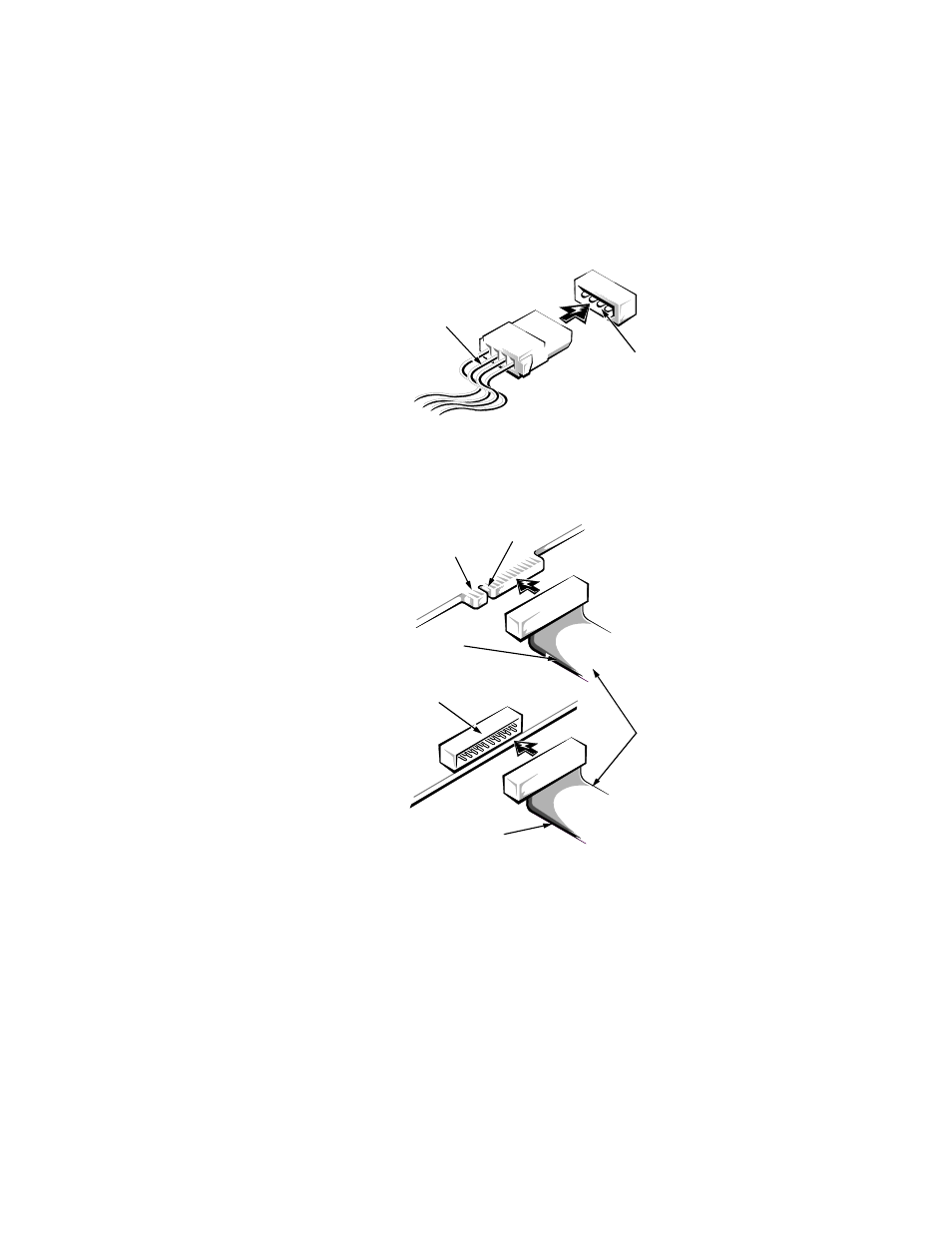
When installing a drive, you connect two cables—a DC power cable and an interface
cable—to the back of the drive. Your drive’s power input connector (to which you con-
nect the DC power cable) resembles the connector shown in Figure 7-4.
)LJXUH '& 3RZHU &DEOH &RQQHFWRU
The drive’s interface connector is a card-edge connector or a header connector, as
shown in Figure 7-5.
)LJXUH 'ULYH ,QWHUIDFH &RQQHFWRUV
When attaching the interface cable to a drive, be sure to match the colored strip on
the cable to pin 1 of the drive’s interface connector. For the location of pin 1 on the
drive’s interface connector, see the documentation that came with the drive.
When disconnecting an interface cable from the system board, be sure to press in on
the locking tabs on the cable connector before disconnecting the cable. When attach-
ing an interface cable to the system board, be sure that the locking tabs snap into
place, ensuring that the cable is firmly attached to the connector on the system board.
DC power cable
power input
connector
header connector
on drive
interface
cables
card-edge connector on drive
colored strip
notch
colored strip