Figure 3-26, T of the chassis. figure 3-26 – Dell PowerEdge C6100 User Manual
Page 100
100
Installing System Components
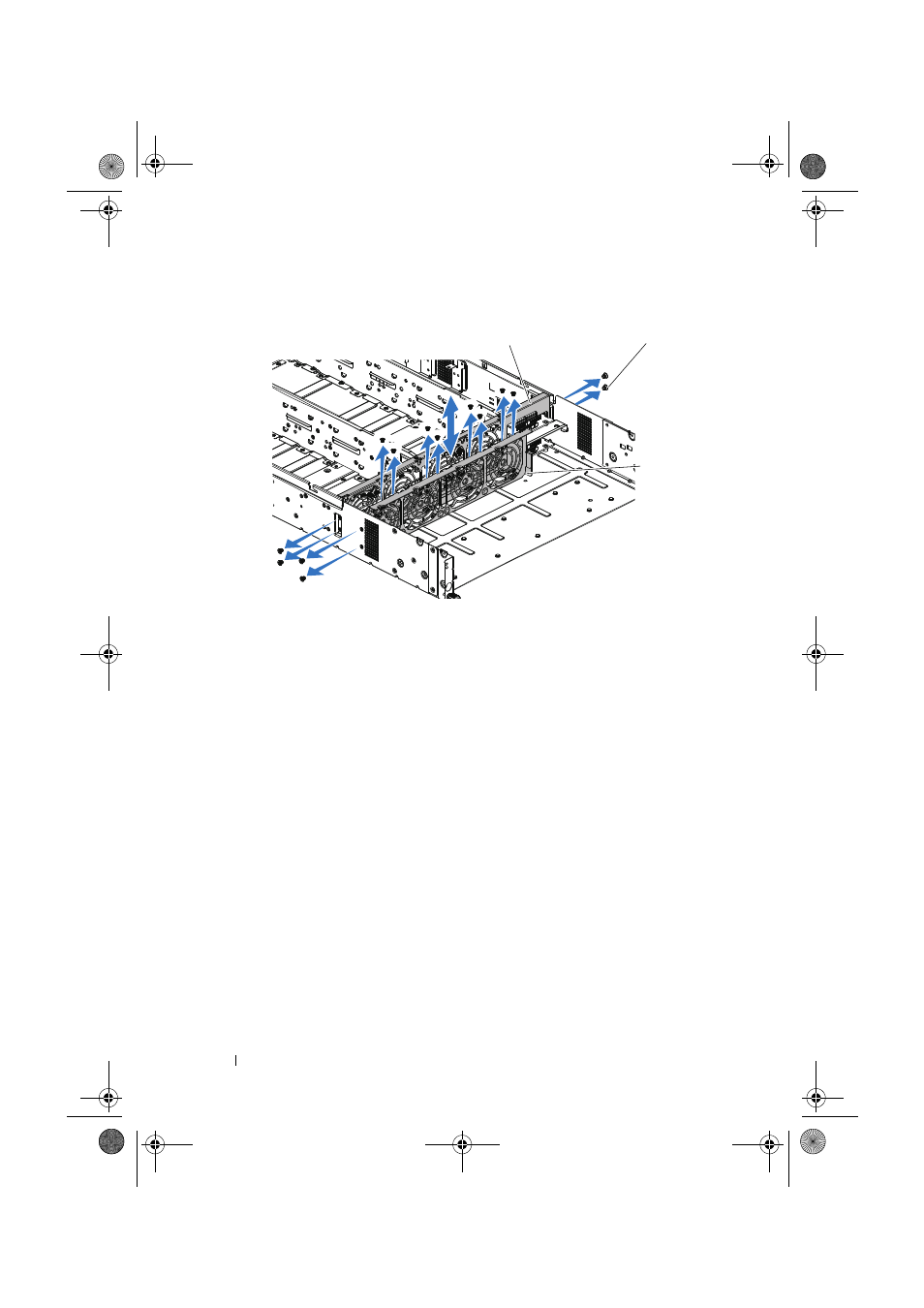
Figure 3-26.
Removing and Installing the Cooling-Fan Brackets
7 Remove the screws that secure the upper midplane to the midplane holder.
8 Disconnect all the cables from the upper midplane. See Figure 5-9.
Note the routing of the cable underneath the tabs on the chassis as you
remove them from the system. You must route these cables properly when
you replace them to prevent the cables from being pinched or crimped.
9 Lift the upper midplane out. Figure 3-27.
1
cooling fan bracket (long)
2
screw (14)
3
cooling fan bracket (short)
1
3
2
book.book Page 100 Thursday, March 4, 2010 4:38 PM
See also other documents in the category Dell Computers:
- Inspiron 530 (2 pages)
- OptiPlex 755 (248 pages)
- OptiPlex 755 (622 pages)
- OptiPlex 755 (528 pages)
- OptiPlex 755 (82 pages)
- OptiPlex 755 (45 pages)
- OptiPlex 760 (76 pages)
- OptiPlex 760 (203 pages)
- OptiPlex 745 (360 pages)
- OptiPlex 745 (428 pages)
- OptiPlex 745 (212 pages)
- OptiPlex 780 (14 pages)
- OptiPlex 780 (89 pages)
- OptiPlex 780 (10 pages)
- OptiPlex 780 (74 pages)
- OptiPlex 780 (80 pages)
- OptiPlex 780 (73 pages)
- OptiPlex 780 (40 pages)
- OptiPlex GX620 (338 pages)
- OptiPlex GX620 (221 pages)
- OptiPlex GX620 (294 pages)
- Inspiron 530 (226 pages)
- OptiPlex 960 (Late 2008) (16 pages)
- OptiPlex GX260 (100 pages)
- OptiPlex GX260 (235 pages)
- OptiPlex FX160 (Late 2008) (20 pages)
- OptiPlex FX160 (Late 2008) (132 pages)
- OptiPlex FX160 (20 pages)
- OptiPlex 210L (128 pages)
- OptiPlex 210L (300 pages)
- OptiPlex 210L (258 pages)
- OptiPlex 210L (150 pages)
- OptiPlex 210L (130 pages)
- OptiPlex 320 (266 pages)
- OptiPlex 320 (356 pages)
- OptiPlex 320 (44 pages)
- OptiPlex 320 (140 pages)
- OptiPlex 320 (132 pages)
- OptiPlex 320 (312 pages)
- OptiPlex GX240 (182 pages)
- OptiPlex GX240 (144 pages)
- OptiPlex GX240 (121 pages)
- OptiPlex GX240 (86 pages)
- OptiPlex GX240 (283 pages)
- OptiPlex GX240 (298 pages)