Installation – Baumer NE131 User Manual
Page 12
www.baumer.com
NE131
12
Installation
Connection
The instrument is connected via the enclosed
plug-in screw terminals. Maximum size of core
cross section is 1.5 mm
2
.
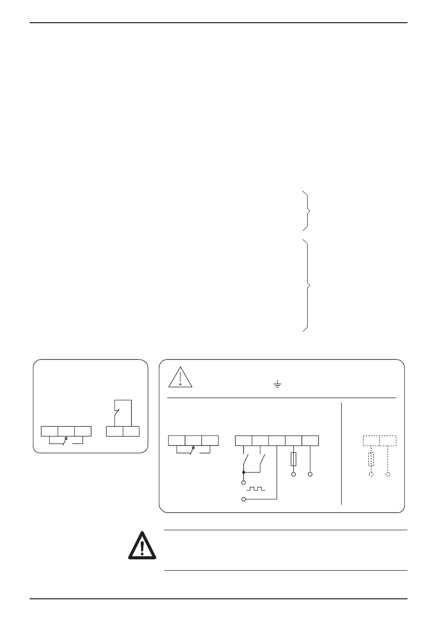
Assigned contacts
1 Voltage supply AC/DC (pls refer to nameplate)
2 Voltage supply AC/DC (pls refer to nameplate)
3 Common connection Count, Reset
4 Count
5 Reset
6 Main cont. (nor. open)
7 Main cont. (changeover)
8 Main cont. (nor. closed)
9 Keylock
10 Keylock
11 Not assigned
12 Not assigned
13 Leader cont. (nor. open)
14 Leader cont. (changeover)
15 Leader cont. (nor. closed)
Terminal assignment
0D[9
WHUPLQDOWRWHUPLQDO
WRWHUPLQDO
)LQDOFRQWDFW
5HVHW
&RXQW
9ROWDJH VXSSO\
P$0
9a
+]
9
9
+]
9ROWDJH VXSSO\
P$0
3UHFRQWDFW
.H\ORFN
a«
a«
a«
±
±
For litz connection use connector sleeves with
insulating enclosures. For voltage supply please
refer to nameplate..
Main contact = P1
with 1 preset
Main contact = P2
with 2 presets
Assignment 9-15 only
available for counter
models with 2 presets
Leader contact = P1
with 2 presets