3 setup – Cooper Instruments & Systems Model 7i Professional Force/Torque Indicator User Manual
Page 6
Model 7i Digital Force / Torque Indicator
User’s Guide
5
off), a message appears, “BATTERY VOLTAGE TOO LOW. POWERING OFF”. An audio
tone will sound and the indicator will power off.
The indicator can be configured to automatically power off following a period of inactivity. Refer to the
Other Settings section for details.
If battery replacement is necessary, it can be accessed by separating the two halves of the indicator.
Refer to the Setup section for details.
3 SETUP
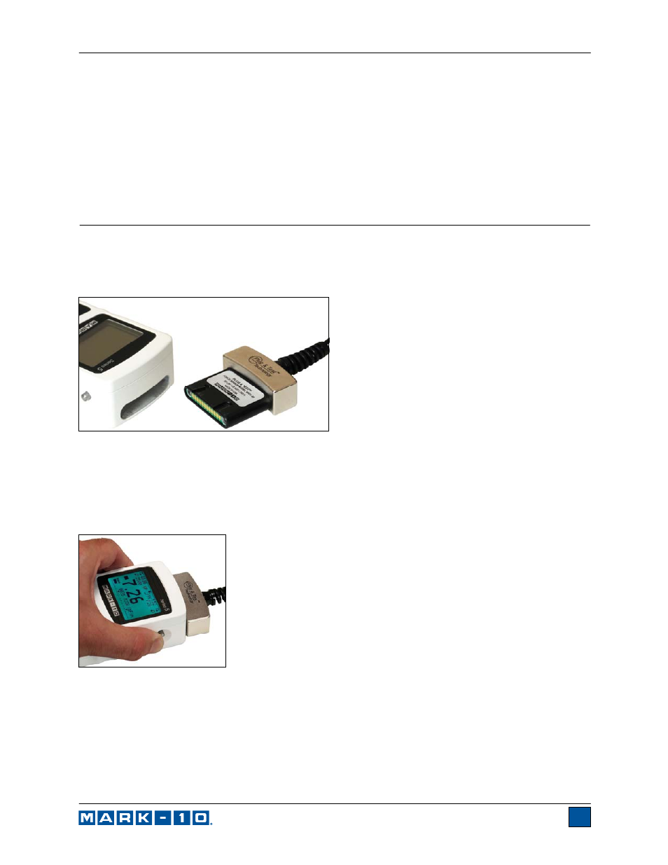
3.1 Connecting a sensor
The Plug & Test
TM
connector must be inserted into the receptacle of the 7i, 5i, or 3i indicator with the side
marked “Plug & Test
TM
Technology” facing up (see Fig. 3.1). When fully inserted, the connector will lock
into place with a “click”.
Fig. 3.1
Appropriate orientation of Plug & Test
TM
connector. Sensor model
number, serial number, and load capacity may be found on the
labels affixed to the connector.
To release the connector, press both buttons on either side of the indicator housing to release the sensor
(see Fig. 3.2). Pull the connector completely out of the indicator by holding the curved aluminum section.
DO NOT pull on the cable or strain relief.
Fig. 3.2
Press both buttons on either side of the
indicator housing to release the Plug
& Test
TM
connector.
3.2 Sensor connector orientation
In order to accommodate a variety of testing requirements, the orientation of the Plug & Test
TM
connector
may be set up in either of the two positions shown below. To change the orientation, loosen the two
captive screws on the back side of the housing, separate the two housing halves, rotate one half 180
degrees, and reassemble. Contact between the two halves is made by the spring pins and contact pads