Cooper Instruments & Systems Model 7i Professional Force/Torque Indicator User Manual
Page 12
Model 7i Digital Force / Torque Indicator
User’s Guide
11
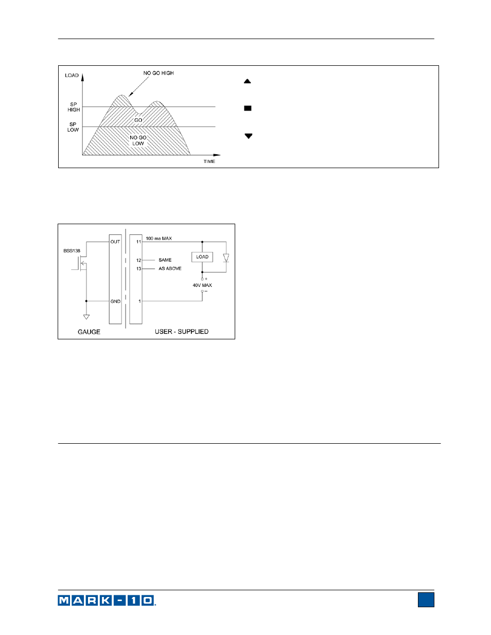
– the displayed value is greater than the upper
set point (NO GO HIGH)
– the displayed value is between the set points
(GO)
– the displayed value is less than the lower set
point (NO GO LOW)
Note: Set point indicators and outputs reference the displayed reading, not necessarily the current live
load.
6.3 Set Point Outputs Schematic Diagram
6.4 Using Set Points to Control a Mark-10 Motorized Test Stand
When using set points to stop/cycle Mark-10 motorized test stands, the upper and lower set points must
be set to opposite measuring directions. Both set points must be set, even if the intended application is
to stop/cycle at only one of the set points. The opposite set point should be a value sufficiently large that it
does not get triggered during the course of the test.
For certain Mark-10 test stands, the upper and lower set point directions are reversed.
7 BREAK DETECTION
The break detection function identifies when a sample has broken, clicked, slipped, or otherwise reached
a peak load and then fell by a specified percentage drop. Upon detection of the break, the indicator can
perform several automatic functions, depending on the mode in which break detection is enabled, as
follows:
1. Transmit the peak reading (Auto Output).
2. Save the peak value to memory (Auto Storage).
3. Zero the primary and peak readings (Auto Zero).
4. Toggle a pin (for example, to stop crosshead movement on a Mark-10 motorized test stand).
Break detection functions and settings are configured from a central location, and apply to any mode in
which it is enabled. Refer to the Operating Modes section for details on configuring each mode.
7.1 Configuration