Cooper Instruments & Systems Model 7i Professional Force/Torque Indicator User Manual
Page 32
Model 7i Digital Force / Torque Indicator
User’s Guide
31
Other Commands
AOFFn
Auto-shutoff. n=0-30 minutes. 0=auto shutoff disabled
SAVE
Save current settings in nonvolatile memory
LIST
List current settings and status
Following is an example LIST output:
V1.00;LBF;CUR;FLTC8;FLTP1;AOUT00;AOFF5;FULL;IPOL0;OPOL0;MIT;POL;B0
All fields are separated by “;”. The first field shows the firmware version, the last field shows the remaining
battery power (B0=full charge, B3=minimum power). All other fields show the status of settings and
features using the same abbreviations as the commands to set them.
Any detected errors are reported back by means of the following error codes:
*10
Illegal
command
*11
Not
applicable
*21
Invalid
specifier
*22 Value too large
15 CALIBRATION
15.1 Initial Physical Setup
The sensor should be mounted vertically to a test stand or fixture rugged enough to withstand a load
equal to the full capacity of the sensor. Certified deadweights, torque arms/wheels, and/or master load
cells should be used, along with appropriate mounting brackets and fixtures. Caution should be taken
while handling such equipment.
15.2 Calibration Procedure
In the interests of simplicity and brevity, the following instructions use force terminology only. Such
wording is displayed only when a force sensor is being calibrated. When a torque sensor is being
calibrated, the terms COMPRESSION and TENSION are replaced by CLOCKWISE and COUNTER-
CLOCKWISE, respectively.
1. Select
Calibration from the menu. The display appears as follows:
The sensor can be calibrated at up to 10 points in each direction. Enter the number of calibration
points for each direction (compression and tension or clockwise and counter-clockwise). At least
one point must be selected for each direction. For single-direction sensors such as Mark-10’s
Series R02, only one direction is allowed.
Note: To achieve the accuracy specification of ±0.1% + sensor, it is recommended to calibrate
the sensor at 5 or more even increments in both the tension and compression directions. For
example, a sensor with capacity of 10 lbF should be calibrated at 2, 4, 6, 8, and 10 lbF loads in
each direction.
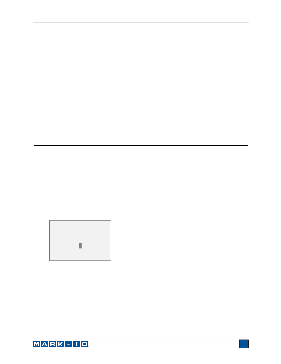
2. To escape the Calibration menu at any time, press ESCAPE. The display appears as follows:
CALIBRATION
Enter # cal points
(1 to 10)
Compression:
5
Tension:
5