Cooper Instruments & Systems Model 7i Professional Force/Torque Indicator User Manual
Page 18
Model 7i Digital Force / Torque Indicator
User’s Guide
17
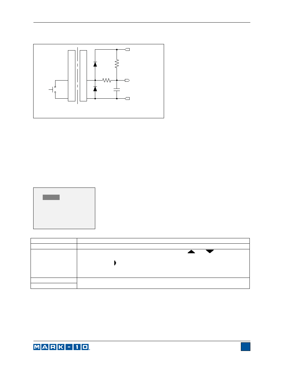
9.5.1 External Trigger Schematic Diagram
14
GND
1
IN
22k
SWITCH UNDER TEST
GAUGE
+3.3V
TO MICROPROCESSOR
0.1 uF
GND
BAT54SLT1G
330 Ohm
(NO OR NC)
USER - SUPPLIED
Note: Custom cabling is required to connect to a switch, or to connect a switch and a Mark-10 test stand
simultaneously.
9.6 Data Capture (CAPT)
This mode of operation is used to capture and store continuous data in the indicator’s memory. The
capture frequency can be adjusted to accommodate quick-action as well as longer duration tests. Saved
data can be downloaded in bulk via USB or RS-232.
9.6.1 Configuration
After Data Capture has been enabled, it may be selected by pressing the MODE key until CAPT is
displayed. The display appears as follows:
Note: For best performance, it is recommended to keep the current reading filter at its lowest value. See
Digital Filters section for details.
9.6.2 Start Condition
Data capture is initiated when the Start Condition has been triggered. Several triggers are available, as
shown below:
Function Description
Enabled
If enabled, CAPT appears as one of the operating modes.
Period
The capture period may be adjusted by pressing the
and
keys to change
the value of the hours (H), minutes (M), seconds (S), and fractions of seconds (x)
fields. Press the key to advance to the next field.
Available settings:
Hours: 0-24, Minutes: 0-59, Seconds: 0-59,
Fraction of Seconds: 0.00007-0.99995, in 0.00007 (70 μS) increments.
Start Condition
See following sub-sections for details.
Auto Settings
DATA CAPTURE
*
Enabled
Period (H:M:S.x)
00 :00 :00.00007
+ Start Condition
+ Stop Condition
+ Auto Settings