Cooper Instruments & Systems Model 7i Professional Force/Torque Indicator User Manual
Page 24
Model 7i Digital Force / Torque Indicator
User’s Guide
23
If no option is selected, this screen will be displayed indefinitely, or until battery power has been depleted.
11 FOOTSWITCH
This feature allows the indicator to execute up to three functions in sequence, separated by an optional
delay, when the External Trigger input (pin 14 on the I/O connector) transitions from a high level to a low
level. The ET input has an internal pull-up resistor. One suggested method for triggering the footswitch
sequence would be to provide a relay or contact closure to ground.
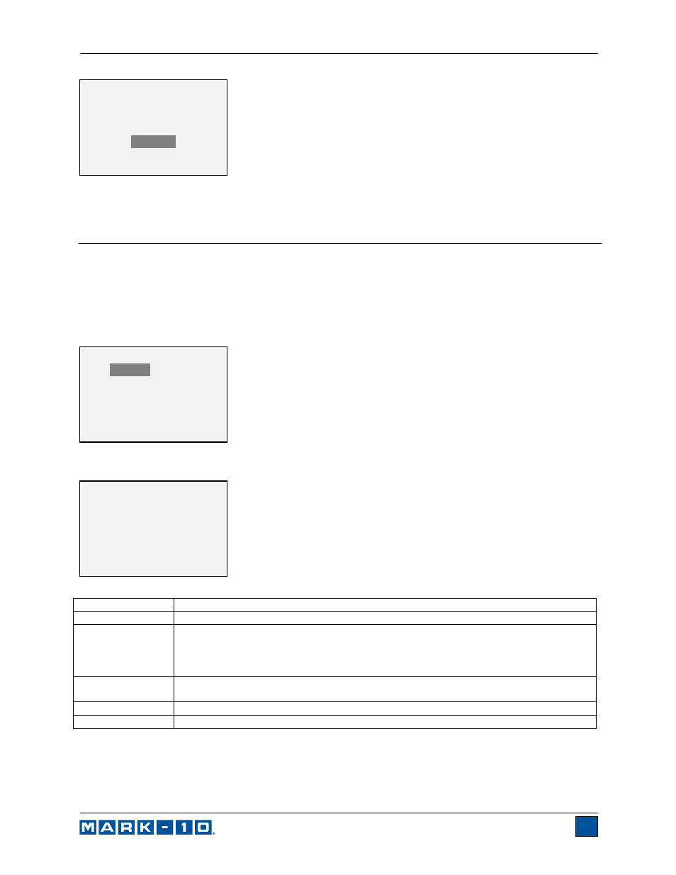
To enable the footswitch settings, select Footswitch from the menu. The display appears as follows:
Select “+ More” for additional options:
Function Description
Enabled
Press ENTER to enable, and an asterisk appears.
Step 1 / 2 / 3
Set the desired command.
Available commands:
?, ?C, ?PT, ?PC, ?A, Z, CLR, PM, DATA Key, and NONE.
DATA Key simulates a press of the DATA key. Explanations for other commands
may be found in the Communications and Outputs section.
Delay 1 / 2 /3
Set the desired delay between commands.
Available settings:
0 – 5 sec. in 1 sec. increments, and 5 – 60 in 5 sec. increments.
Active Low (NO)
Normally open contact between pin and ground.
Active High (NC)
Normally closed contact between pin and ground.
FOOTSWITCH 2
Step 3: NONE
Active Low (NO)
Active High (NC)
FOOTSWITCH
Enabled
Step 1: NONE
Delay 1: 0 sec.
Step 2: NONE
Delay 2: 0 sec.
+ More
*** WARNING ***
DATA IN MEMORY
WILL BE LOST
CANCEL
POWER OFF