Cooper Instruments & Systems Model 7i Professional Force/Torque Indicator User Manual
Page 29
Model 7i Digital Force / Torque Indicator
User’s Guide
28
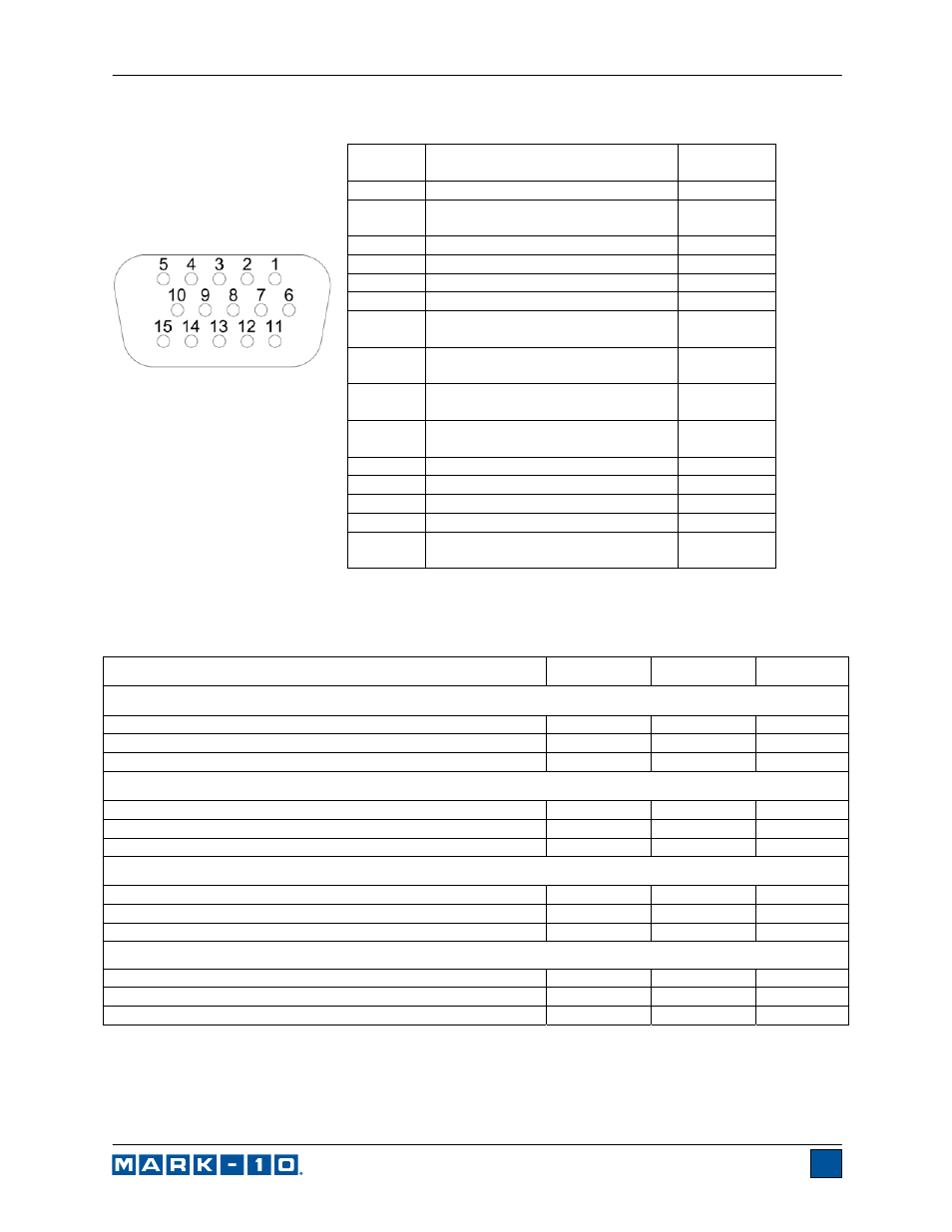
14.5 I/O Connector Pin Diagram (DB-9HD-15 female)
* Maximum voltage: 40V.
** The output assignments depend on several factors described in the table below. Output functions
always reference the primary reading on the display, regardless of the current mode.
Load
Pin 11
Pin 12
Pin 13
Upper and Lower Set Points are C / CW
Greater than or equal to upper set point
On
Off
Off
Between upper and lower set points
Off
Off
On
Less than or equal to lower set point
Off
On
Off
Upper and Lower Set Points are T / CCW
Greater than or equal to upper set point
Off
On
Off
Between upper and lower set points
Off
Off
On
Less than or equal to lower set point
On
Off
Off
Upper Set Point is C / CW, Lower Set Point is T / CCW
Greater than or equal to upper set point, in C / CW
Off
On
Off
Between upper and lower set points
Off
Off
On
Greater than or equal to lower set point, in T / CCW
On
Off
Off
Upper Set Point is T / CCW, Lower Set Point is C / CW
Greater than or equal to upper set point, in T / CCW
Off
On
Off
Between upper and lower set points
Off
Off
On
Greater than or equal to lower set point, in C / CW
On
Off
Off
C = compression, T = tension, CW = clockwise, CCW = counter-clockwise
Pin No.
Description
Input /
Output
1 Signal
Ground
---
2 *
Tension / Counter-clockwise
Overload *
Output *
3
RS-232 Receive
Input
4 RS-232
Transmit
Output
5 +12V
DC
Output
6 Analog
Output
Output
7 *
Compression / Clockwise
Overload *
Output *
8
Mitutoyo Clock or
Output Bit 2 (mutually exclusive)
Output
9
Mitutoyo Data or
Output Bit 0 (mutually exclusive)
Output
10
Mitutoyo Request or
Input Bit 3 (mutually exclusive)
Input
11 **
Set Point Pin 1 (SP1)**
Output **
12 **
Set Point Pin 2 (SP2)**
Output **
13 **
Set Point Pin 3 (SP3)**
Output **
14 External
Trigger
Input
15 *
Mitutoyo Ready or
Output Bit 1 (mutually exclusive) *
Output *