Monitor setup, Marker setup (option), Monitor setup marker setup (option) – Great Plains YP625PD Operator Manual User Manual
Page 21
Great Plains Manufacturing, Inc.
Preparation and Setup
17
02/23/2011
401-754M
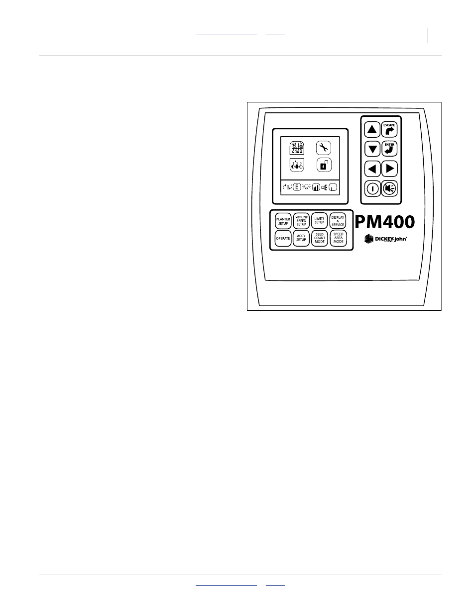
Monitor Setup
Refer to Figure 21
The standard DICKEY-john
®
PM400 system monitors
the following elements of a YP625PD planter:
• Seeds at each row unit seed tube.
• Ground speed.
See “Seed Monitor Console Installation” on page 108.
Refer to the DICKEY-john
®
PM300-332-400 Planter Monitor Operator’s Manual
(11001-1372) for monitor operations.
After installation, and prior to first field use, the monitor
must be setup with the row spacing and speed sensor
constant, as well as your preferences for information
display. Row count is auto-assigned, but any other
DICKEY-john
®
defaults are not likely to be correct for
your planter.
Row spacing data may be found in the Appendix.
For speed setup, Great Plains recommends using the
122 m (400-foot) calibration described in the
DICKEY-john
®
manual, rather than using the theoretical
“# of pulses” shown in Appendix B. Perform the
calibration run in representative field conditions, as soil
conditions, surface looseness and other tillage practices
can cause variations in the effective rolling radius of the
ground drive wheel.
Prior to each planting session, set any desired limits for
speed and population for the current crop.
Marker Setup (Option)
Prior to first use, check and adjust:
• “Marker Speed Adjustment” on page 111.
Prior to first use, and whenever changing row spacings,
set or reset:
• “Marker Extension” on page 111.
Prior to each planting session, check and adjust:
• “Marker Disk Adjustment” on page 47.
Figure 10
Monitor Primary Screen
31807