Speed settings, Pulses per rev, Wheel pulses per 400 feet – Great Plains ADC2220 Operator Manual User Manual
Page 61: Speed calibration, Wheel pulses per 400 feet speed calibration
Great Plains Manufacturing, Inc.
Loup II Monitor Operation
57
2012-10-17
167-073M
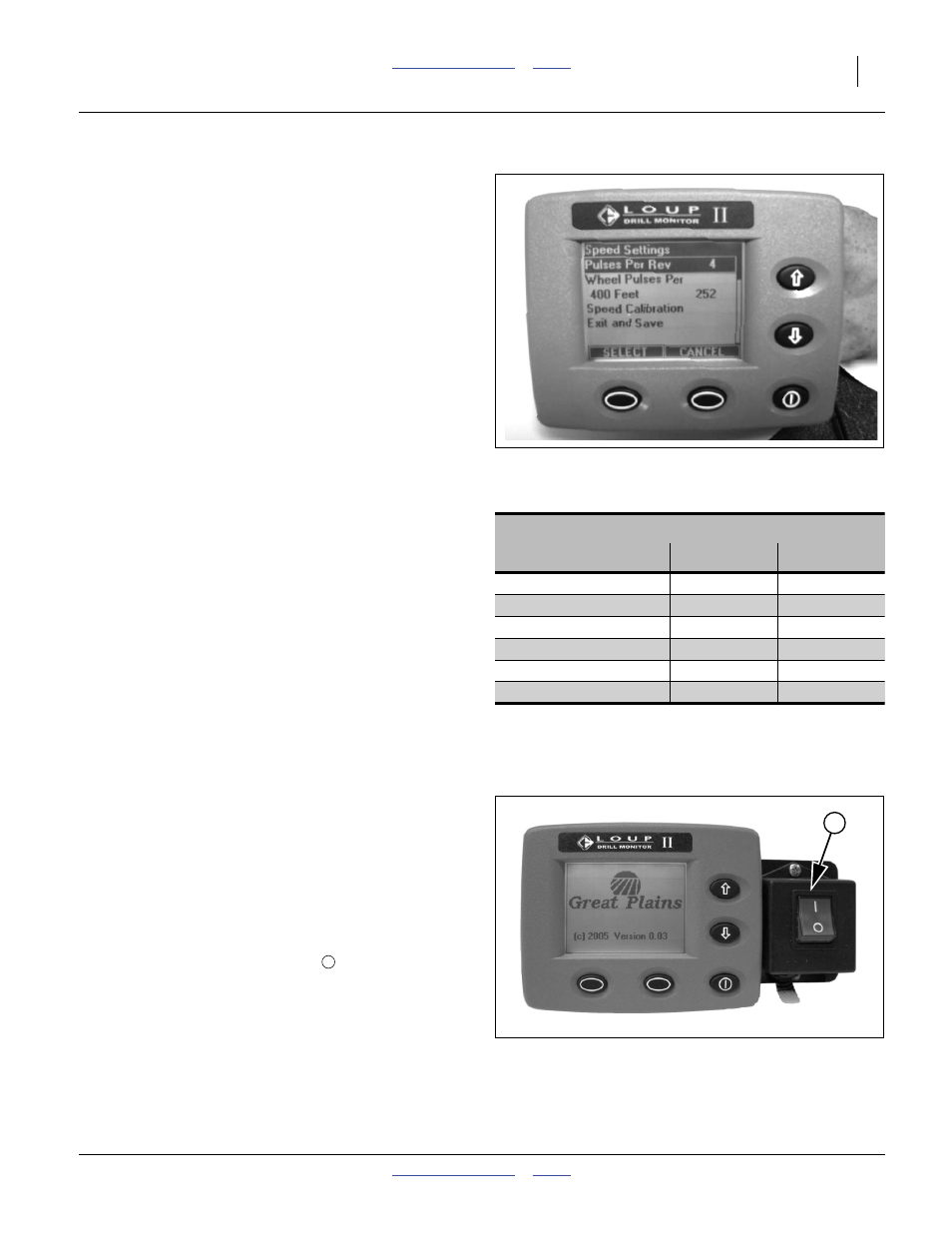
Speed Settings
Refer to Figure 67
Pulses Per Rev
Pulses per Rev (revolution) are the number of magnets
the implement mounted speed sensor sees in one
revolution of the ground drive clutch shaft. The magnet
assembly is on the inner end of this shaft.
The factory default is 4 pulses per rev (PPR), which is
correct for current ADC2220 carts. Older carts may have
2 or 4 magnets on the shaft, visible as short metal rods
in the polymer magnet housing.
Wheel Pulses Per 400 Feet
This is the ground speed calibration number for a
implement mounted speed sensor. Refer to page 57 for
calibration instructions.
The factory default for speed PPR is:
252
for compatibility with older monitors as a service
replacement. This is approximately correct only for
ADI334.
Approximate PPR values for various drills are shown in
the table at right. Do not rely on these values for planting.
Use them as a cross-check of your calibrated rate. If your
calibrated PPR is significantly different from the table, it
may indicate a mechanical fault, or that your cart is not
correctly setup for your drill.
Speed calibration is necessary for all air drills, including
ADI334. The default PPR is incorrect for newer drills, and
the table values at right are only approximate.
Re-calibration is recommended as tires wear or field
conditions change (which can alter effective rolling radius
of tires). Always cross-check the monitor reported speed
with the tractor speedometer or other reference.
Speed Calibration
All new systems require a ground speed calibration to
ensure accurate area totals and accurate ground speed
readings. To complete the calibration, measure a course
400 feet (121.9 m) long preferably on level ground with a
start and finish point. The drill must be in the down
position throughout this procedure.
Refer to Figure 68
1.
Position the drill at the start of the course, in lowered
field position. Set clutch switch
to On.
Note: During the calibration the monitor is looking for the
number of pulses produced from the drill mounted
sensor or in the case of radar, the number of radar
pulses. The monitor does not display 400 when the
speed calibration is complete rather it displays the
pulses counted in 400 feet.
Figure 67
Speed: Pulses per Revolution
29055
Pulses per Rev (Speed)
in 400 feet (121.9 m)
Imperial
a
a. Use “Imperial” for U.S. customary units.
Metric
ADI334
253
253
ADI345
331
331
CTA4000
296
296
CTA4000HD
296
296
NTA3010
226
226
NTA3510
253
253
Figure 68
Clutch Switch On
29013
1
1