Adjusting disk angle & side gauge wheels – Great Plains PD8070 Operator Manual User Manual
Page 54
50
PD8070
Great Plains Manufacturing, Inc.
401-479M
2014-07-23
Adjusting Disk Angle & Side Gauge Wheels
Refer to Figure 53
For 51 mm (2 inch) planting depth, adjust side gauge
wheel angle so wheels contact row unit disks at the
bottom of wheel - in clock hand notation, between
4:00 and 8:00 o’clock. Check with row units in soil so
wheels are held up.
At the same time, keep side gauge wheels close to
opener disks so openers do not plug with soil or trash.
Note: Wheels should be out far enough so disks and
wheels turn freely.
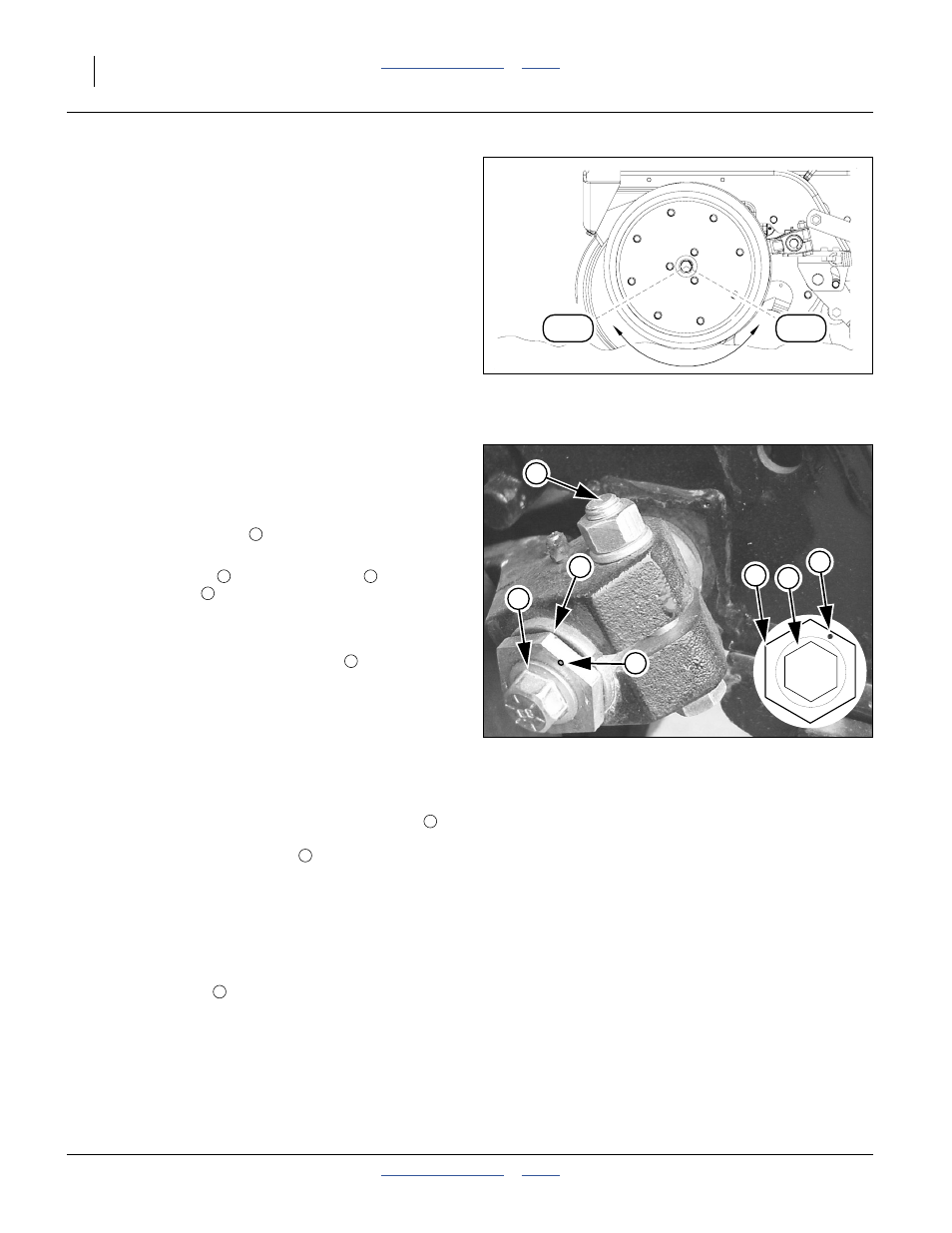
Refer to Figure 54
To adjust side gauge wheels:
1.
Raise planter slightly removing weight from side
gauge wheels.
2.
Loosen hex-head bolt
. Move wheel and arm out
on o-ring bushing.
3.
Loosen pivot bolt
. Turn hex adjuster
so
indicator notch
is at 1 o’clock.
Note: Use this as the starting point for adjustment.
4.
Move wheel arm in so side gauge wheel contacts
row unit disk. Tighten hex-head bolt
to clamp arm
around bushing and shank.
5.
Check wheel-to-disk contact at 51 mm (2 inch)
planting depth. Lift wheel 51 mm (2 inch) and
release. When let go, wheel should fall freely.
• If wheel does not contact disk at bottom to area where
blade leaves contact with soil, move hex adjuster until
wheel is angled for proper contact with disk.
• If wheel does not fall freely, loosen hex-head bolt
and slide wheel arm out just until wheel and arm move
freely. Retighten hex-head bolt
according to grade:
1
⁄
2
inch Grade 5 bolt, 102 N-m (75 foot-pounds).
1
⁄
2
inch Grade 8 bolt, 149 N-m (110 foot-pounds).
Note: Use “Torque Values Chart” on page 100 for
reference.
6.
Keep turning hex adjuster and moving wheel arm
until the wheel is adjusted properly. When satisfied,
tighten pivot bolt
to 149 N-m (110 foot-pounds).
4:00
8:00
Figure 53
Opener-Gauge Wheel Contact
17812
4
2
3
1
Figure 54
Disk/Gauge Wheel Adjustment
25455
3
4
2
1
2
3
4
1
1
1
2