Marker disk adjustments, Marker disk angle, Marker disk angle axis – Great Plains PD8070 Operator Manual User Manual
Page 45: Marker folding speed, Marker disk angle marker disk angle axis
Great Plains Manufacturing, Inc.
Adjustments
41
2014-07-23
401-479M
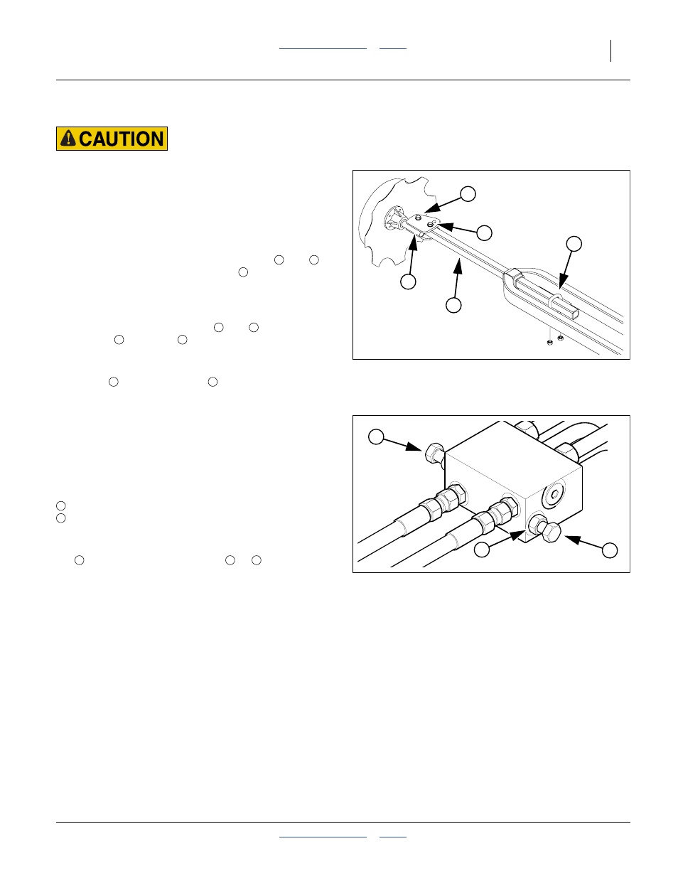
Marker Disk Adjustments
Sharp Object Hazard:
Use caution when making adjustments in this area.
Marker disks may be sharp.
The mark left by the marker disk may be changed by
several methods.
Refer to Figure 38
Marker Disk Angle
1.
To change the angle of cut, loosen bolts
and
,
rotate disk assembly around bolt
and retighten
bolts.
Marker Disk Angle Axis
2.
The disk may be mounted to throw dirt in or out. To
reverse throw, remove bolts
and
, remove
spindle
from tube
and remount it with the
spindle axis behind the tube.
3.
If vertical angle adjustment is needed, loosen the
U-bolt
, remove the tube
, rotate it 90 degrees,
and re-secure it.
Marker Folding Speed
The marker hydraulic system is equipped with needle
valves to control how fast each marker operates. The
needle valves are built into the sequence valve body,
which is located directly below the slow-moving-vehicle
placard. There are two hex adjustment heads, one for
controlling:
marker speed up (folding) and
marker speed down (unfolding).
Excessive folding speeds can cause marker damage.
With the tractor engine at an operating rpm, loosen jam
nut
and adjust the needle valve
or
to limit the
marker to a safe operating speed.
Make sure all adjustments are made with warm oil. Fold
the marker up and down a few times and recheck for
pinching and kinking of hoses.
Figure 38
Marker Angle Adjustments
25450
6
5
4
7
8
4
5
5
4
5
7
8
6
8
Figure 39
Marker Rate Valve
15029
2
1
3
1
2
3
1
2