Appendix 2: sequence of operation block diagram – Tweco 6000GST Merlin Plasma Cutting CE Slave Power Supply User Manual
Page 60
APPENDIX
A-2
Manual 0-2653
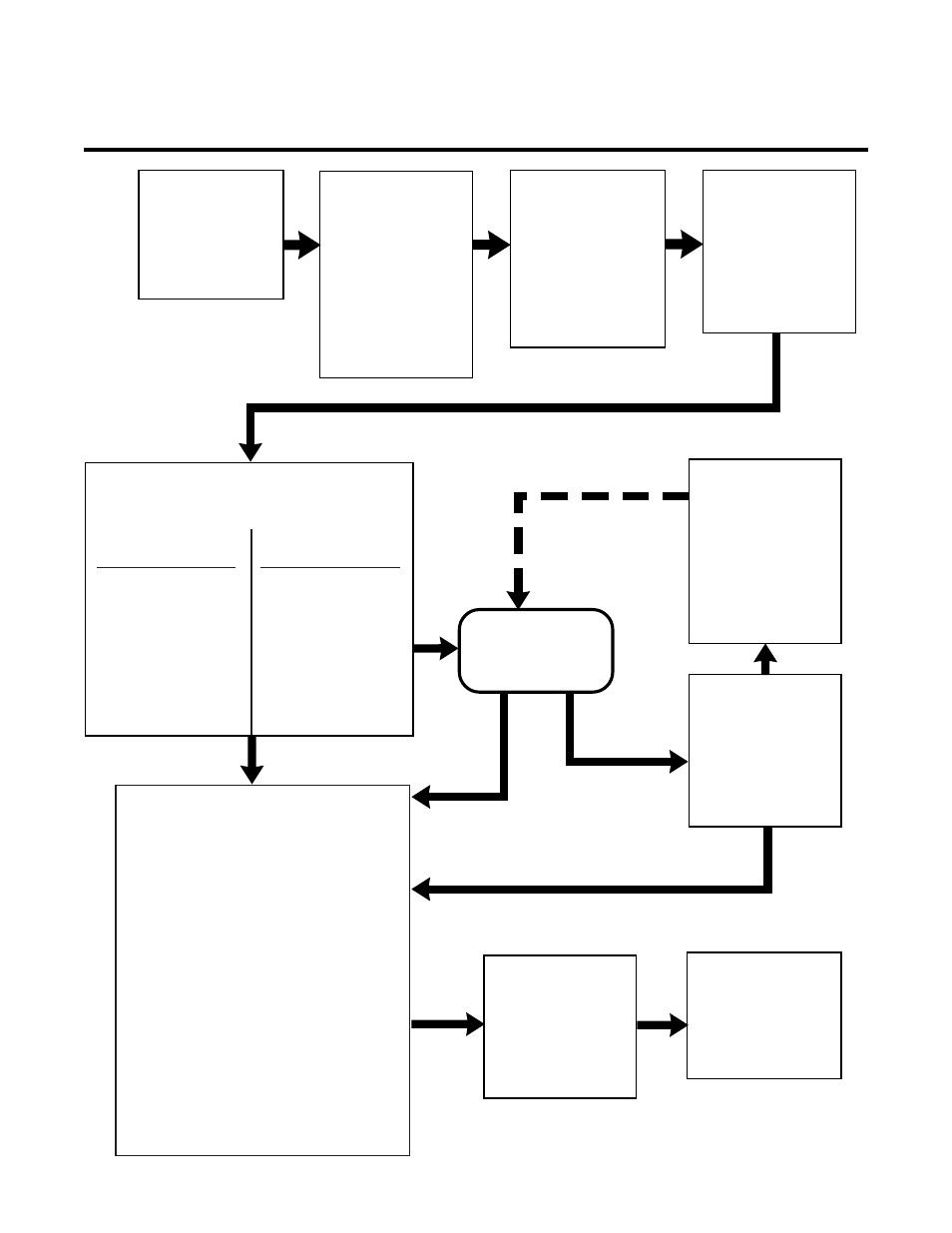
APPENDIX 2: SEQUENCE OF OPERATION
BLOCK DIAGRAM
A-03298
ACTION
Close external
disconnect switch
RESULT
• Power to system
ACTION
Enable ON at Remote
or TB2
ON/OFF switch to ON
RESULT
• AC indicator ON
• TEMP indicator ON
• GAS indicator ON
• Fan and Pump ON
• 40 sec auto-purge
ACTION
Gas Control Module
MODE switch to SET
RESULT
• Gas solenoids open,
gases flow to set
pressures and flows
• GAS indicator ON
ACTION
Gas Control Module
MODE switch to RUN
RESULT
• Gas flow stops
• GAS indicator OFF
• Power circuit ready
PILOT ARC
ACTION
Torch removed from
work
RESULT
• Main arc stops
• Pilot arc auto-restart
if enabled
• PILOT indicator ON
ACTION
Torch moved to within
1/8 - 3/8 inch of work
RESULT
• Main arc transfer
• PILOT indicator OFF
• Pilot arc off
ACTION
Open external
disconnect
RESULT
• No power to system
ACTION
ON/OFF switch to OFF
RESULT
• AC indicator OFF
• TEMP indicator OFF
• Fan and Pump OFF
ACTION
Torch de-activated by torch switch
release or remote device
RESULT
• Main arc stops
• Main contactor opens
(Logic PC Board Rev AE or Earlier Only
• DC indicator OFF
• Pilot and PILOT indicator OFF
NOTE
If torch is activated during post-flow the pilot
arc will immediately restart. If within range
of work, main arc will transfer.
After post-flow:
• Main contactor opens
(Logic PC Board Rev AF or Later Only
• Gas solenoids close, gas flow stops
• GAS indicator OFF
ACTION
Protect eyes and activate torch
RESULT
• Gas indicator ON
• Gas pre-flow
• Main contactor closes
• DC indicator ON
• Pilot contactor closes
• PILOT indicator ON
• Pilot arc established
Logic PC Board
Rev AE or Earlier
RESULT
• Main contactor closes
• Gas indicator ON
• Gas pre-flow
• DC indicator ON
• Pilot contactor closes
• PILOT indicator ON
• Pilot arc established
Logic PC Board
Rev AF or Later