03 specifications & design features – Tweco 6000GST Merlin Plasma Cutting CE Slave Power Supply User Manual
Page 16
INTRODUCTION & DESCRIPTION
2-2
Manual 0-2653
2.03 Specifications & Design
Features
The following apply to the Master Power Supply only:
1. Controls
ON/OFF Switch, Output Current Control, Arc Hour/
Counter Meters
2. Control Indicators
LED Indicators:
AC , TEMP, GAS, DC, PILOT, COOLANT PRES, and
COOLANT COND
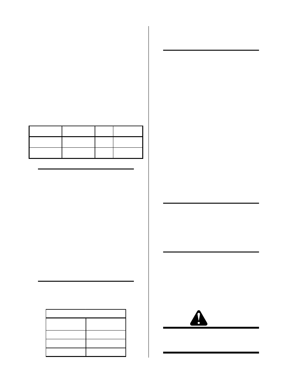
3. Input Power
Vo l ta g e
F re q u e n cy
Ph a s e
A m p erag e
3 80
5 0 or 6 0 H z
3
5 1
4 15
5 0 or 6 0 H z
3
4 7
NOTE
Refer to Appendix 1 for recommended input wir-
ing size, current ratings, and circuit protection re-
quirements.
Amperage depends on input voltage (Refer to Ap-
pendix 1).
4. Output Power
Master Power Supply:
Continuously adjustable by potentiometer from 50
to 150 amps
With Slave Power Supply:
Continuously adjustable by potentiometer from
100 to 300 amps
5. Duty Cycle (see NOTE)
NOTE
The duty cycle will be reduced if the primary in-
put voltage (AC) is low or the DC voltage is higher
than shown in the chart.
Ambient
Temperature
104° F (40° C)
Duty Cycle
100%
Current
150 Amps
DC Voltage
140 vdc
Power Supply Duty Cycle
6. Pilot Modes
Auto-Restart, Pre-Flow Delay, "Recycle Required"
NOTE
Pilot modes 'Auto-Restart' and 'Recycle Required'
not recommended when using oxygen (0
2
) as
plasma gas.
7. CNC Signals
a. Power Supply
Enable, Start/Stop, OK-To-Move, Pilot Sensing Re-
lay (PSR)
b. Remote Control
Full CNC available with Remote Control
8. Coolant Pressure
Internal Coolant Pressure Gauge
Internal Service-adjustable
130 psi (8.8 bar) at zero flow
120 - 125 psi (8.2 - 8.5 bar) at 0.6 gpm (2.6 lpm)
9. Coolant Flow Rate
0.5 gpm (2.2 lpm) with 150 feet of total torch and torch
leads at 70°F (21°C)
NOTE
The flow rate varies with lead length, torch con-
figuration, ambient temperature, amperage level,
etc.
10. Cooling Capacity
4,000 to 10,000 BTU
NOTE
Maximum value based on “free flow” condition.
11. Coolant Reservoir Capacity
2 gallons
Capable of handling a total of 150 feet of torch lead
length
12. Secondary Water
WARNING
The Optional Water Mist Secondary Flow Con-
trol Assembly must be installed when using water
as the secondary.