04 removing skid, 05 input power connections, 06 checking input connections – Tweco 6000GST Merlin Plasma Cutting CE Slave Power Supply User Manual
Page 20
INSTALLATION PROCEDURES
3-2
Manual 0-2653
C. Options and Accessories
Options and Accessories are packaged separately from the
Power Supply.
D. Unpacking Procedure
1. Unpack each item and remove all packing material.
2. Locate the packing list(s) and use the list to identify
and account for each item.
3. Inspect each item for possible shipping damage. If
damage is evident, contact your distributor before pro-
ceeding with installation.
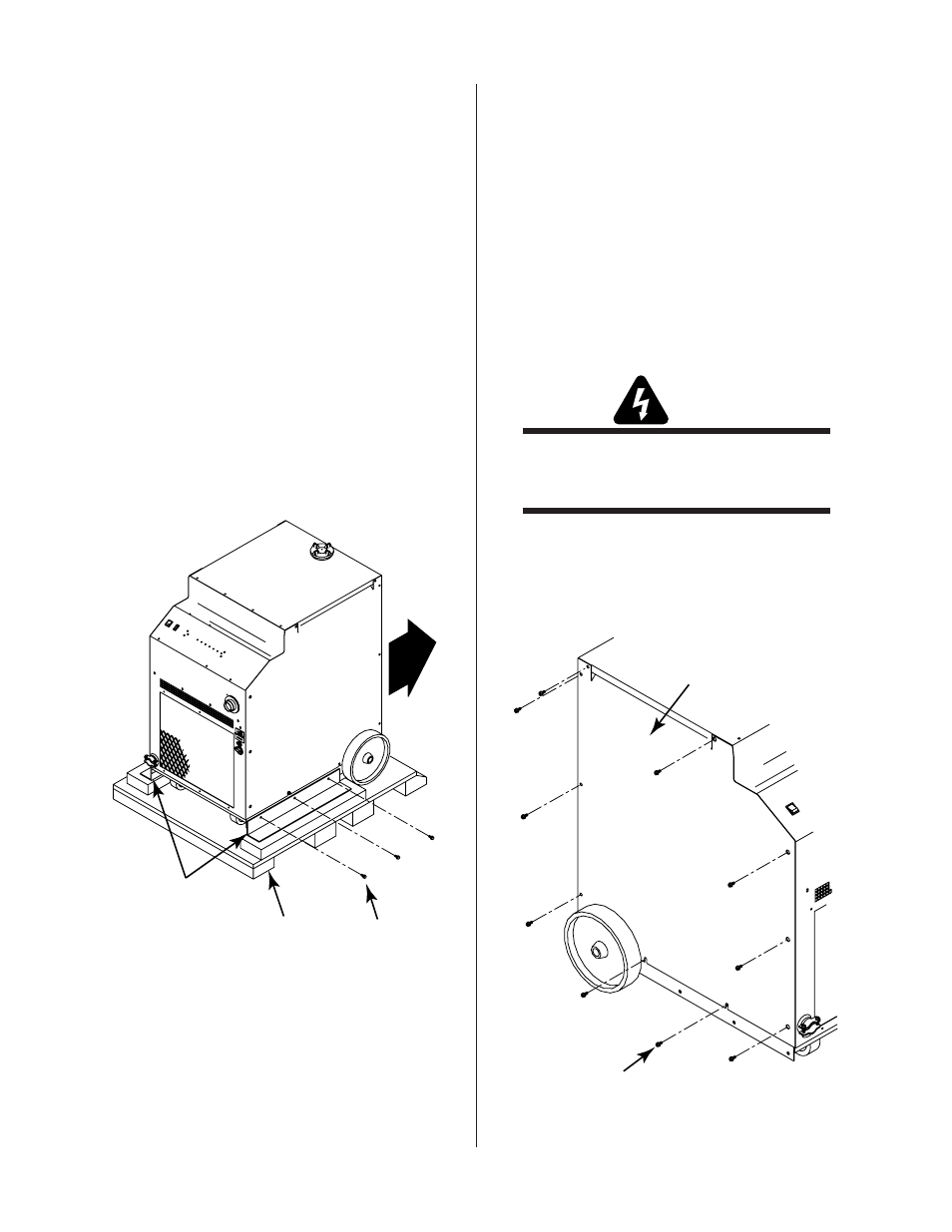
3.04 Removing Skid
The Power Supply is mounted on the skid with two brackets.
Remove the Power Supply from the skid as follows:
1. Remove the six bolts connecting the brackets to the base of
the Power Supply.
A-01760
Three Bolts
(Each Side)
Shipping Brackets
Shipping Pallet
Figure 3-1 Skid Removal From Power Supply
2. Roll the Power Supply off the skid backwards (rear wheels
first).
3.05 Input Power Connections
The Power Supply accepts input voltages from 380/415V, 50 or
60 Hz, three-phase power.
A. Electrical Connections
The power source must conform to local electric code and the
recommended circuit protection and wiring requirements shown
in Appendix 1.
B. Opening Power Supply Enclosure
The left side panel (viewed from the front) of the Power Supply
must be removed to make electrical connections and to select
the proper input voltage.
WARNING
Disconnect primary power at the source before
assembling or disassembling power supply, torch
parts, or torch and leads assemblies.
1. Remove the eight screws which secure the left side
panel (viewed from the front) to the Power Supply.
2. Loosen the two bottom screws in the slotted holes.
Left Side Panel
Screws
(10 Places)
A-01528
Figure 3-2 Opening Power Supply