Figure 3-22 resistance value diagram – Tweco 6000GST Merlin Plasma Cutting CE Slave Power Supply User Manual
Page 35
Manual 0-2653
3-17
INSTALLATION PROCEDURES
Pulser
99
150
Wire #99
Tap
9.0 ohms
At End
R16 (4.5 ohms)
R22 (2.2 ohms)
R21 (2.2 ohms)
Temp Switch
Wire
#96A
Wire #150
Tap
Wire #74
8.5 ohms
12.8" (305 mm)
8.0 ohms
11.2" (279 mm)
7.5 ohms
9.6" (242 mm)
7.0 ohms
8.1" (203 mm)
6.5 ohms
6.5" (164 mm)
6.0 ohms
5.0" (127 mm)
5.5 ohms
3.4" (87 mm)
5.0 ohms
1.9" (44 mm)
4.4 ohms
At End
Wire #96
4.4 ohms
At End
5.0 ohms
13.7" (344 mm)
5.5 ohms
12.3" (311 mm)
6.0 ohms
10.8" (255 mm)
6.5 ohms
9.4" (237 mm)
7.0 ohms
8.0" (203 mm)
7.5 ohms
6.5" (164 mm)
8.0 ohms
5.1" (127 mm)
8.5 ohms
3.7" (90 mm)
9.0 ohms
2.5" (63 mm)
A-01852
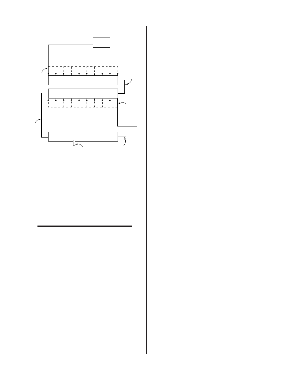
Figure 3-22 Resistance Value Diagram
7. The pilot pulse value is set by positioning the wire
#150 tap on resistor R22. Locate and loosen the
wire #150 tap. From the above Figure find the
ohms value that corresponds to the value that the
wire #99 tap was set to. Measure distance indi-
cated from the right side of R22, where wire #96
attaches and secure the wire #150 tap there.
NOTE
The ohm value shown for the wire #150 tap does
not represent the value of the R22 resistor but in-
stead corresponds to the total resistance of R16,
R22 and R22 set by the wire #99 tap.
8. Test the pilot, if it still sputters move the wire #99
tap to the right, toward wire #96, 1 inch (25.4 mm)
at a time until the pilot no longer sputters.
9. Once there is a good steady pilot, test for the de-
sired transfer height. If the transfer height is not
high enough, between 3/8 inch (9.5 mm) to 1/2
inch (12.7 mm), move the wire #150 tap to the left
on R22, 1 inch (25.4 mm) at a time, until the de-
sired height is obtained.