Tweco 6000GST Merlin Plasma Cutting CE Slave Power Supply User Manual
Page 34
INSTALLATION PROCEDURES
3-16
Manual 0-2653
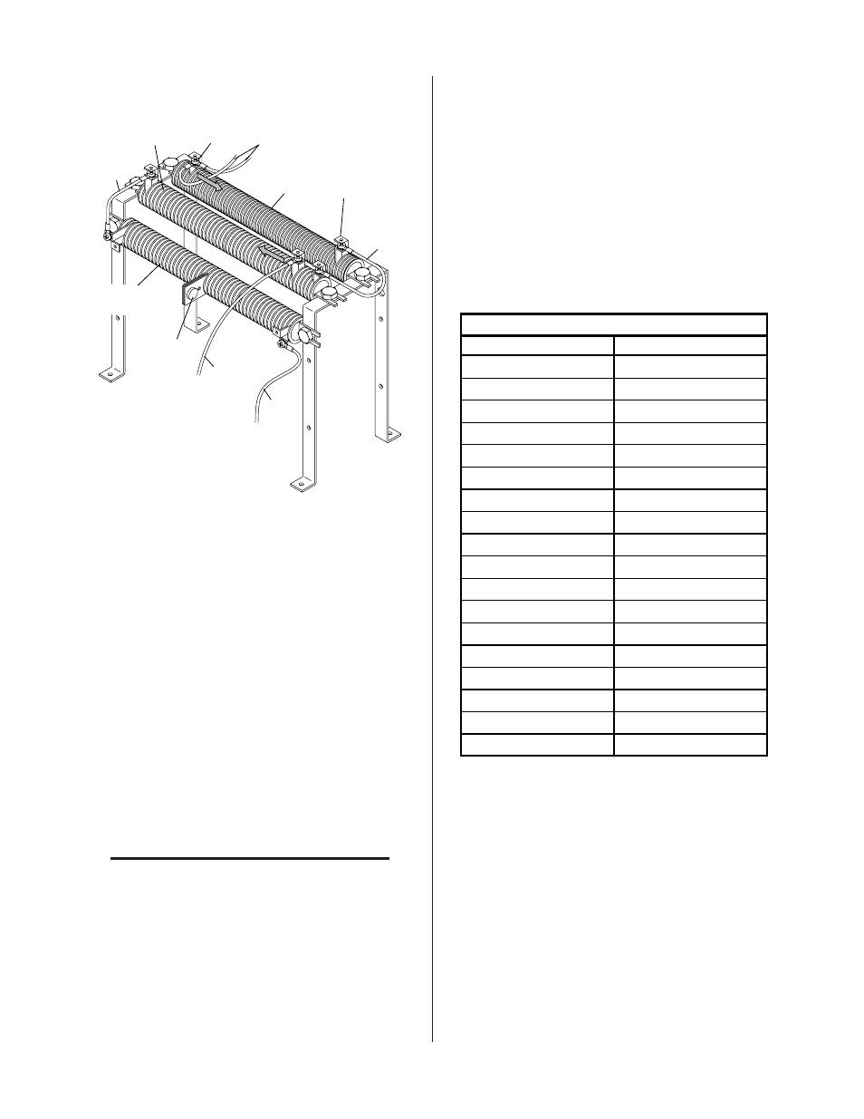
Wire
#96A
Pilot Resistor
R16
Clamp
Clamp
A-01853
Wire
#150
Pilot Resistor
R21
Pilot Resistor
R22
Wire
#74
Wire #99
Wire
#96
Temp
Switch
Figure 3-21 Location Of Pilot Resistors (Viewed From
The Front Of Power Supply)
3. Check the busbar configuration on the input terminal
board to determine which range the power transformer
is set for.
4. Measure the level of the AC line voltage being sup-
plied to the Power Supply.
5. To determine the recommended pilot resistor setting
use the following table as follows:
a. Find the voltage that is nearest what was measured
above.
b. Note the ohms value for the voltage. Example: If
the measured voltage is 360, then the pilot resistor
value is 6 ohms.
NOTE
Voltages that are from 410 to 420V require values
from 8.5 or 9 to 4.5 ohms. If the voltage is near one
of these points it is best to set for the lower ohms
value.
The reason is because within each range the Power
Supply will automatically select a high or low tap on the
transformer secondary. This is based on the input AC
line voltage at the time the Power Supply is turned ON.
If the line voltage is near one of these points the volt-
age might measure, for example, 410 VAC and the pilot
resistor setting should be 9 ohms to have a good pilot.
The next time the system is turned ON, the input AC
line voltage may have gone up to 420VAC causing the
pilot to sputter because 420VAC requires setting of 4.5
ohms.
Pilot Resistor Setting vs. Input Line Voltage
Input (VAC)
Ohms
340
5
350
5.5
360
6
370
6.75
380
7.25
390
8
400
8.5
410
9
420
4.5
430
5
440
5.5
450
6
460
6.5
470
7
480
7.5
490
8
500
8.5
510
9
6. Wires are attached to the pilot resistors with metal
clamps or taps. Locate and loosen the screw that
secures the wire #99 tap on resistor R16. Deter-
mine, from the Figure below, the correct position
for the tap on R16 and tighten the screw.
Example:
To set for 6 ohms measure 5” from the right side
of R16, where wire # 96 attaches, and secure the
#99 tap at that position.