Tweco 6000GST Merlin Plasma Cutting CE Slave Power Supply User Manual
Page 30
INSTALLATION PROCEDURES
3-12
Manual 0-2653
B. Computer Control Interface (CNC)
NOTE
Used when Remote Control RC6010 or Standoff
Control SC11 are not used.
The computer control interface (CNC) allows a mechanized sys-
tem to interface with a computer or other control device.
NOTE
Refer to Section 4.03-D for more information on
the CNC connections.
CNC cables can be interfaced to the Power Supply using
one of the following methods:
NOTE
Refer to Appendix 7 for CNC Interface Schematic.
• Connector (J15) at the rear of the Power Supply
• Internal terminal strip in the Power Supply
Depending on the equipment ordered and the cables sup-
plied connect the CNC cable per one of the following:
1. Using supplied CNC cable
Connect the supplied Power Supply/CNC Cable
to the Power Supply rear connector J15 labelled
REMOTE CONTROL.
2. Using customer supplied CNC Cable
a. Remove the Left Side Panel from the Power
Supply as viewed from the front of the unit.
b. Locate the internal terminal strip (TB2) near
the heatsink.
c. Feed the CNC cable through the small strain
relief at the rear of the Power Supply.
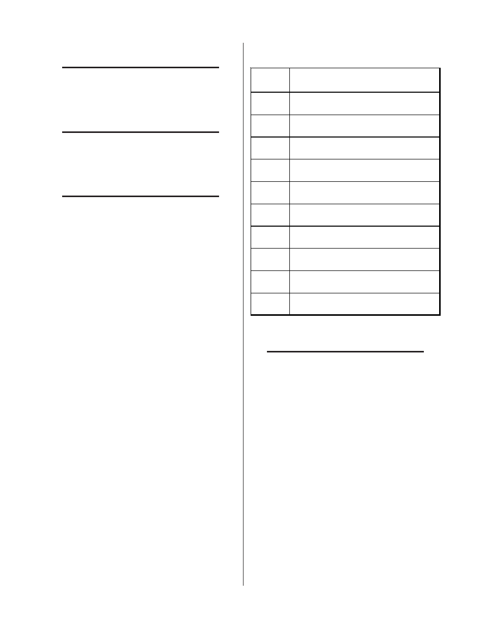
d. Connect the CNC cable to the terminal strip
(TB) per the following chart (see NOTES after
chart):
TB2
Connection
Description
1
One Side of Enable Signal (Common)
2
Other Side of Enable Signal (+15 vdc)
3
One Side of START(Low)/STOP (High) Signal
(+15 vdc)
4
Other Side of START (Low)/STOP (High) Signal
(Common)
5
Not Used
6
Not Used
7
One Side of Pilot Sensing Relay (PSR) - Dry
Contacts
8
Other Side of Pilot Sensing Relay (PSR) - Dry
Contacts
9
One Side of OK-To-Move Signal (Refer to
Section 4.06)
10
Other Side of OK-To-Move Signal (Refer to
Section 4.06)
NOTES
Connections to TB2 positions 1 through 4 are ac-
tivated with a switch or contact closure.
If Remote Control is not used the Enable Signal
circuit must be closed.
Connections TB2-7 and TB2-8 are normally open
(NO) contacts.
Connections TB2-9 and TB2-10 are selectable for
normally open (NO) contacts or 24 VAC.
e. Secure the CNC cable by tightening the two
screws on the strain relief.
f. Reinstall the Left Side Panel.