B. control front panel, C. rear panel, Figure 4-3 front control panel – Tweco 6000GST Merlin Plasma Cutting CE Slave Power Supply User Manual
Page 38
OPERATION
4-2
Manual 0-2653
5. Power Lead Strain Relief
Strain relief to secure the power lead to the Power
Supply after it is installed.
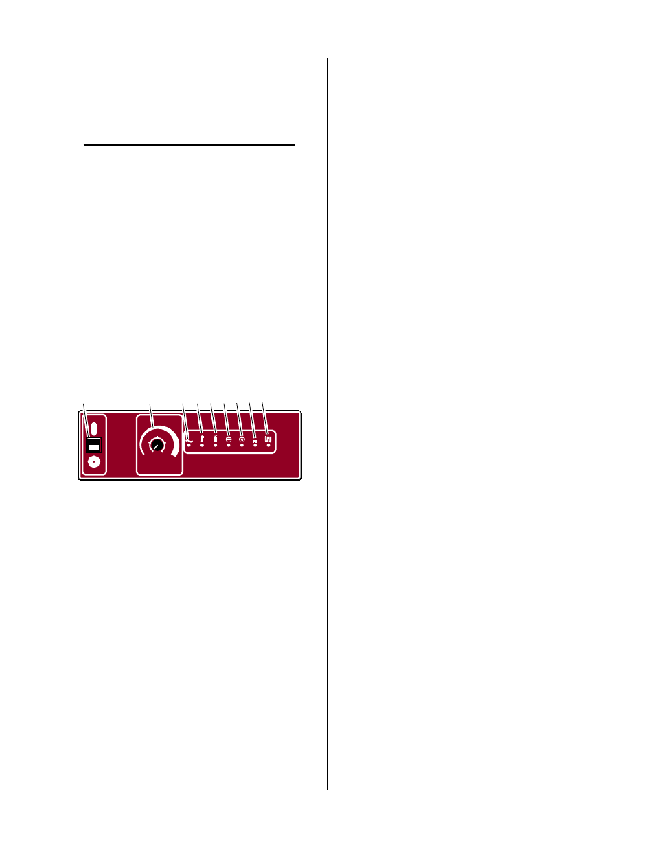
B. Control Front Panel
NOTE
This panel is the access cover to the Logic Control
and Switching PC Boards.
1. ON/OFF Switch
ON position activates all system control circuits when
remote or CNC enable is ON.
OFF position deactivates control circuits.
2. Current Control (Dual Scale)
Selects output current for the application on various
materials and thicknesses. Current control is disabled
when Remote Control is used.
Current is adjustable for the application as follows:
• 50 to 150 amps for single power supply
• 100 to 300 amps for dual power supplies
A-01756
1
2
3
4 5 6 7 8 9
GST
Gas
Stepping
Technology
TM
O N
O F F
A M P S
D U
D U A L
A L
1 5 0
7 5
1 2 5
5 0
1 0 0
S I N G L E
A C
T E M P
G A S
P R E S .
C O N D .
D C
P I L O T
C O O L A N T
3 0 0
1 0 0
2 0 0
1 5 0
2 5 0
Figure 4-3 Front Control Panel
3. AC Power Indicator
Green light indicates AC power is being supplied to
the system when the ON/OFF switch is in ON posi-
tion.
4. TEMP Indicator
Green light indicates proper operating temperature.
Red light indicates overheating. Unit must be allowed
to cool.
5. GAS Indicator
Yellow light indicates plasma gas pressure switch is
satisfied when gas is flowing to the torch.
6. COOLANT PRES. (Coolant Pressure) Indicator
Yellow light indicates adequate coolant flow.
7. COOLANT COND. (Coolant Conductivity) Indica-
tor)
Yellow light indicates proper coolant conductivity.
Light out indicates excessive coolant conductivity (re-
sistivity less than 0.1 megaohms per centimeter). Re-
place coolant and de-ionizer cartridge.
8. DC Indicator
Yellow light indicates voltage is present at the power
supply output and cutting current is available.
9. PILOT Indicator
Yellow light indicates pilot arc contactor closure. Light
goes out when cutting arc is established. Refer to
Section 4.06-A and -B, Auto Restart Function.
C. Rear Panel
1. Fan Assembly
Fan used to move the air across the internal compo-
nents for cooling purposes.
2. PLASMA AIR Gas Input Fitting
1/4 NPT female gas fitting used to supply the air
plasma gas to the system.
3. PLASMA O
2
(Oxygen) Gas Input Fitting
1/4 NPT female gas fitting used to supply the oxy-
gen (O
2
) plasma gas to the system.
4. PLASMA N2 (Nitrogen) Gas Input Fitting
1/4 NPT female gas fitting used to supply the
nitrogen(N2) plasma gas to the system.
5. PLASMA Ar/H2 (Argon/Hydrogen) Gas Input Fit-
ting
1/4 NPT female gas fitting used to supply the
nitrogen(N2) plasma gas to the system.
6. Coolant Reservoir and Filler Cap
The coolant reservoir is located under the top panel
cover. The coolant reservoir supplies the system with
coolant to cool the torch parts during operation. The
maximum capacity of the reservoir is two gallons of
coolant.
Inside the reservoir, in the filler neck, is a basket and
a deionizer bag. The bag removes charged particles
from the coolant after it is returned to the reservoir.
If the coolant in the reservoir breaks down because
of these charged particles then a sensor on the reser-
voir will cause the COOLANT COND indicator to
go OFF.