10 connecting torch supply leads – Tweco 6000GST Merlin Plasma Cutting CE Slave Power Supply User Manual
Page 27
Manual 0-2653
3-9
INSTALLATION PROCEDURES
2. Connect the tap water supply hose to the input of a Water
Pressure Regulator.
3. Connect the output of the water regulator to the fitting
marked SECONDARY H2O (water) on the rear panel of the
Power Supply.
NOTE
The water source does not need to be deionized,
but in water systems with extremely high mineral
content a water softener is recommended.
SECONDARY H
2
0
Supply
A-01764
Figure 3-10 Secondary Water Connection
3.10 Connecting Torch Supply
Leads
The Torch Supply Leads interfaces the Master Power Sup-
ply to the Arc Starter Box and the Gas Control Module.
The Torch Supply Leads is made up of individual hoses
and cables that must be connected.
NOTES
Refer to the Arc Starter Box Instruction Manual
0-2654 for details on installation of the Arc Starter
Box.
Refer to the Gas Control Module Instruction
Manual 0-2641 for details on installation of the
Gas Control Module.
The Torch Supply Leads components connects directly to a
bulkhead inside the Master Power Supply and to connections
inside the right side panel. Connect the Torch Supply Leads
components as follows:
WARNING
Primary power should NOT BE APPLIED when
working inside the power supply.
1. Open the front panel access panel to gain access to
the bulkhead.
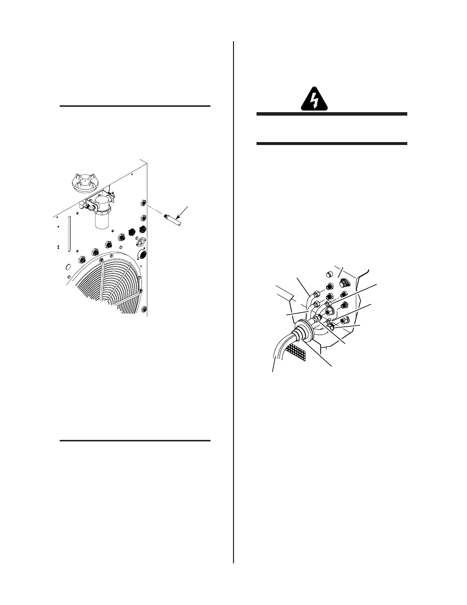
2. Feed the six Torch Supply Lead Hose Assemblies on
the Torch Supply Leads components through the boot
on the front panel of the Master Power Supply.
3. Connect the six hose assemblies onto the mating con-
nections at the internal bulkhead of the Master Power
Supply per the following figure.
Secondary
Gas Lead
Torch Supply Leads
Supply Leads Boot
Coolant Return
Lead
Coolant Supply
Lead
Plasma
Gas Lead
A-01770
Secondary H
2
0
Lead
Master Power Supply
Bulkhead
Pre-Flow N2
Gas Lead
Figure 3-11 Torch Supply Leads Hose Connections
To Master Power Supply
4. Connect the end of the Pilot Lead, two wires, to the
Master Power Supply as follows:
a. Remove the right side panel from the Master Power
Supply.
b. Feed the Pilot Lead, two wires, through the small strain
relief at the front panel of the Master Power Supply.
c. Remove the nut and star washer on the ground termi-
nal of the pilot connection inside the power supply.