14 lifting options, 15 pilot resistor adjustment, 13 master/slave parallel cable connection – Tweco 6000GST Merlin Plasma Cutting CE Slave Power Supply User Manual
Page 32
INSTALLATION PROCEDURES
3-14
Manual 0-2653
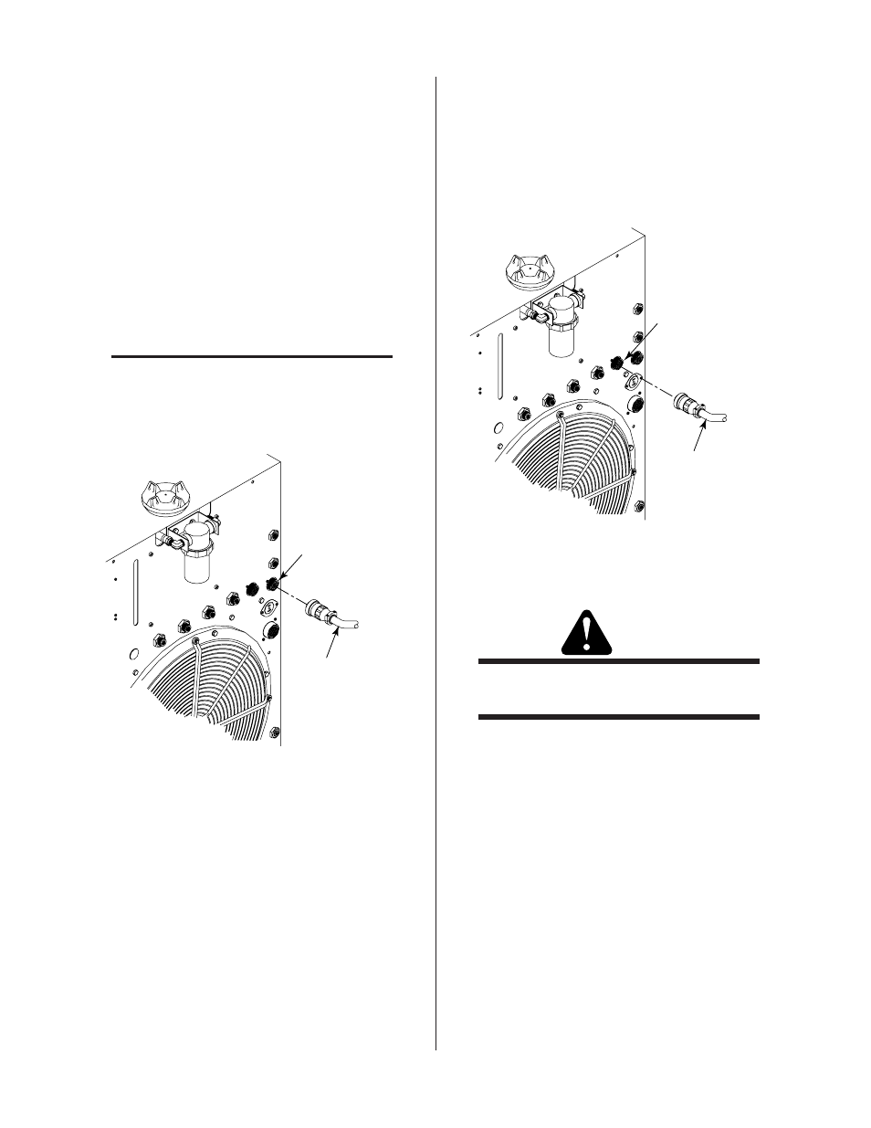
E. Gas Control Module Connection
The Gas Control Module (GCM6000) allows setting pressures
and flows of various multiple plasma and secondary gases con-
nected to the Power Supply. The proper plasma and secondary
gas is selected with switches on the front panel of the Gas
Control Module. The pressures and flows are set for the se-
lected gases with pressure regulators and flowmeters on the
front panel.
1. Connect the Gas Control Module control cable to the
connector marked GAS CONTROL (J55) on the rear
panel of the Power Supply.
2. Connect the other end of the cable to the Gas Control
Module rear panel J56 connector.
NOTE
Refer to the Gas Control Module Instruction
Manual 0-2641 for more information on the
GCM6000 Gas Control Module.
A-01767
Cable From
Gas Control Module
GAS
CONTROL J55
Connector
Figure 3-18 Optional Gas Control Interface Connection
3.13 Master/Slave Parallel Cable
Connection
The interface between the Master and Slave Power Sup-
ply is made through the Parallel Cable. Connect one end
of the cable to the rear of the Master Power Supply at
PARALLEL CONNECTOR J54. The other end connects
to the rear of the Slave Power Supply at J15.
A-01769
Cable To
Slave Power Supply
PARALLEL
CONNECTOR J54
Figure 3-19 Parallel Cable Connection
3.14 Lifting Options
WARNING
Do not lift a power supply equipped with a cylin-
der rack running gear.
The recommended method for lifting the power supply
is to use a forklift as follows:
1. Approach from the front or rear of the unit.
2. Place the forks between the rear wheels or the front
casters.
3. Center the forks under the unit and carefully check for
proper balance before lifting.