tekmar 406 House Control Installation User Manual
Page 6
©
2012 406_D
-
11/12
6
of
48
External Power Supply
It is strongly recommended that a transformer with an in-line
fuse be used in order to protect the transformer from high
currents. The tekmar Transformer 009 includes a fuse.
Connect the 24 V (ac) leads from the transformer to the C
and R terminals marked “Input Power” on the 406.
tekmarNet
®
2 Thermostats (tN2)
The 406 is designed to operate with tekmarNet
®
2 Thermostats.
They provide the heating and cooling control for each zone,
and communicate with any other tekmarNet
®
device on the
system.
Connect the tN2 terminals from each thermostat to the cor-
responding tN2 terminals for each zone on the 406.
Zone Valves
Wire the zone valves to the C and Vlv terminals on the 406.
End switches on zone valves are not required when using
the 406.
tN4 Expansion Terminals
The 406 uses the Expansion tN4 and C terminals to com-
municate with additional thermostats, setpoint controls, and
other tekmarNet
®
devices. Connect to either the Tank or the
Boil / Mix tN4 and C terminals on the 406.
•
•
•
•
Tank
To add additional Tank water temperature zones to the system,
install a tekmarNet
®
Wiring Center.
Connect the Tank terminals, tN4 and C, on the 406 to the
corresponding tN4 and C Expansion terminals on the ex-
ternal Wiring Center.
Boil / Mix
To add additional Boil or Mix water temperature zones to the
system, install a tekmarNet
®
Wiring Center.
Connect the Boil/Mix terminals, tN4 and C, on the 406 to
the corresponding tN4 and C Expansion terminals on the
external Wiring Center.
Domestic Hot Water (DHW) or Setpoint Call
When the control receives a DHW Call or Setpoint Call for heat
it will override Outdoor Reset and Indoor Feedback and operate
the boiler to heat the DHW tank or the Setpoint equipment.
To create a DHW call, wire a dry contact switch to the DHW
call terminals.
To create a Setpoint call, wire a dry contact switch to the
Setpoint call terminals.
•
•
•
•
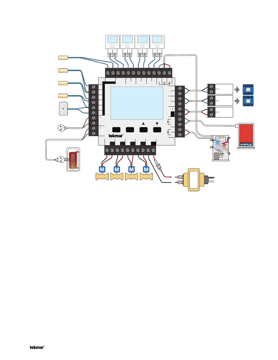
Low Voltage Wiring -------------------------------------------------------------------------------------
-------------------------------------------------------------------------------------
Front Low Voltage Wiring Diagram ---------------------------------------------------------------------
---------------------------------------------------------------------
R
C
L
N
Expansion
tN4 Boil/Mix
Ct
N
4
Modulating
Boiler
—+
Expansion
tN4 Tank
Ct
N
4
tN2 tN2
tN2 tN2
tN2 tN2
tN2 tN2
1
Menu
House Control 406
Item
+
Ta
nk
Com
Boil
HP
Rt
Out
Com
Zone 1
H8009B
Zone 2
Zone 3
Zone 4
tN2 tN2 tN2 tN2 tN2 tN2 tN2 tN2 Rc1 Y1 O/B
Sensors - No P
ow
er
No Power
Call
Call
Mix/DHW
tN4
tN4
CC
Mod dc/mA
Boil / Mix
Tank
Rc2
Y2
Se
tpoint
DHW
R
C
Input Power
Backup
Vlv
C
Vlv
C
Vlv
C
Zone 3
Zone 1
Zone 2
Zone 4
Vlv
C
24 V (ac) Transformer 009
DHW Call
from DHW
Tank Aquastat
(optional)
Setpoint Call
Outdoor Sensor
Mix Supply / DHW
Universal Sensor
Tank Supply
Universal Sensor
Boiler Supply
Universal Sensor
One Stage
Boiler T-T
tekmarNet
®
2 Thermostats
tekmarNet
®
4 Expansion to
Wiring Centers, Timers, or
User Switch
HP Return
Universal Sensor
One or Two Stage
Heat Pump
24 V (ac) Zone Valves