Electrical a406-4, N1 l1 g, N2 g l2 – tekmar 406 House Control Installation User Manual
Page 18: Nl l
©
2012 406_D
-
11/12
18
of
48
Boil Sys
HP Sys
DHW
115 V (ac)
N1
L1
G
115 V (ac)
N2
G
L2
to pump grounds
to pump grounds
N
N
L
L
Back of House Control 406
R
C
L
N
Expansion
tN4 Boil
Ct
N
4
Tank Sys
Mix Sys Pump
Tank Sys Pump
DHW Pump
Transfer Pump
Boil Sys Pump
HP Loop Pmp
Pump
Power (L)
Pump
Power (L)
Variable
Speed Pump
tN2 tN2
tN2 tN2
tN2 tN2
tN2 tN2
Y2 O
Y1
R
(blue)
(red)
(black)
(black)
(black)
(red)
(black)
(black)
(black)
Variable
Speed
314
T
T
Menu
House Control 406
Item
+
Ta
nk
Com
Boil
H
PR
t
O
ut
Com
Zone 1
H8009B
Zone 2
Zone 3
Zone 4
tN2 tN2 tN2 tN2 tN2 tN2 tN2 tN2 Rc1 Y1 O/B
Sensors - No P
ow
er
No Power
Call
Call
Mix/DHW
tN4
tN4
CC
Mod dc/mA
Boil / Mix
Tank
Rc2
Y
2
Se
tpoint
DHW
R
C
Input Power
Backup
Vlv
C
Vlv
C
Vlv
C
Zone 3
Zone 1
Zone 2
Zone 4
Vlv
C
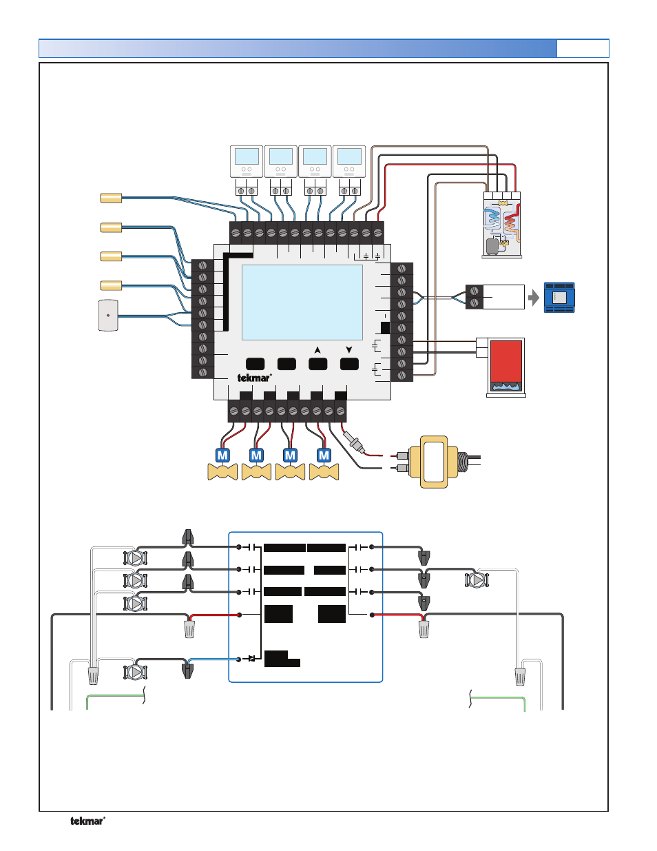
Electrical
A406-4
24 V (ac)
Transformer 009
Heat Pump Return
Sensor (S2)
Tank Sensor (S4)
tekmarNet
®
2 Thermostats
Outdoor
Sensor
(S1)
(P4)
(P6)
(Z1)
(Z2)
(Z3)
(Z4)
Boiler Sensor (S3)
(P3)
(P2)
On/Off
Boiler
Two Stage
Water to Water
Heat Pump
(P1)
DHW Sensor (S5)
- 032 Timer (4 pages)
- 033 4 Timer (12 pages)
- 040 RDM (4 pages)
- 054 RTU (2 pages)
- 055 RTU (2 pages)
- 060 RTU (2 pages)
- 062 RTU (4 pages)
- 063 RTU (8 pages)
- 070 Outdoor Sensor (4 pages)
- 071 Universal Sensor (4 pages)
- 072 10k Slab Sensor (2 pages)
- 073 10k Slab Sensor (2 pages)
- 076 Indoor Sensor (4 pages)
- 077 Indoor Sensor (4 pages)
- 078 Universal Sensor (4 pages)
- 079 Slab Sensor (4 pages)
- 081 Three Outdoor Sensor Module (4 pages)
- 082 Universal Sensor (4 pages)
- 083 Duct Sensor (4 pages)
- 084 Indoor Sensor (4 pages)
- 085 10k Solar Sensor (2 pages)
- 086 Humidity & Temperature Sensor (8 pages)
- 090 Snow/Ice Sensor (8 pages)
- 095 Snow Sensor (8 pages)
- 150 One Stage Setpoint Control (4 pages)
- 152 Two Stage Setpoint Control (4 pages)
- 153 Mixing Setpoint Control (4 pages)
- 155 Difference Setpoint Control (4 pages)
- 156 Difference Setpoint Control (12 pages)
- 157 Difference Setpoint Control (16 pages)
- 161 Setpoint Control Installation (36 pages)
- 161 Setpoint Control User Manuals (12 pages)
- 162 Setpoint Control Installation (32 pages)
- 162 Setpoint Control User Manuals (12 pages)
- 256 Boiler Control (20 pages)
- 257 DHW Control (12 pages)
- 260 Boiler Control (20 pages)
- 261 Boiler Control (20 pages)
- 262 Boiler Control Installation (36 pages)
- 262 Boiler Control User Manuals (4 pages)
- 263 Boiler Control (36 pages)
- 264 Boiler Control (32 pages)
- 265 Boiler Control (36 pages)
- 268 Boiler Control (32 pages)
- 269 One Stage Steam Control (12 pages)