User interface, Setpoint xfr var – tekmar 406 House Control Installation User Manual
Page 21
21 of 48
© 2012 406_D - 11/12
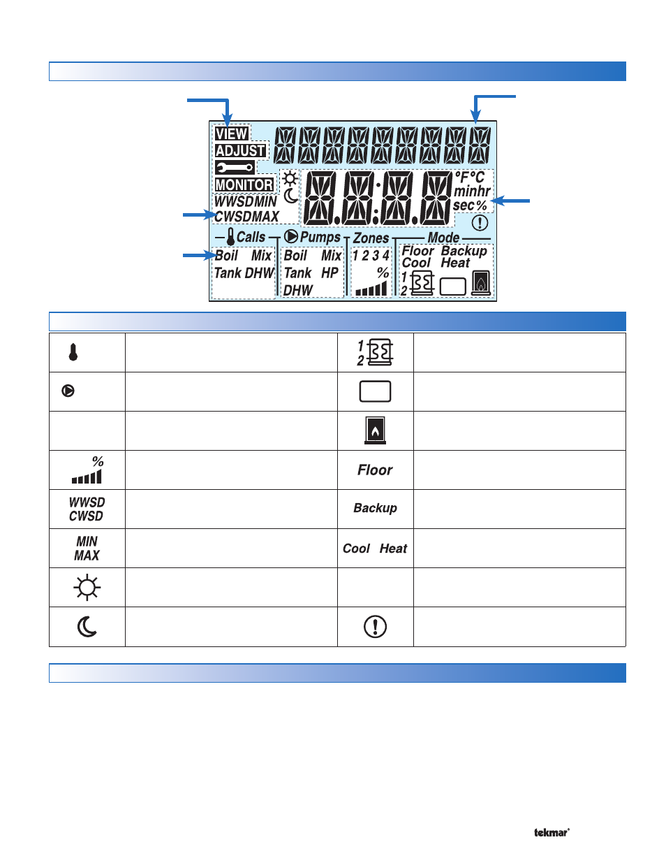
Calls
CALLS
Displays any call for heat or cool the control
is receiving.
Pumps
PUMPS
Displays any pump currently operating.
Zones
1 2 3 4
ZONES
Displays if an on-board zone is operating.
Var
VARIABLE SPEED PUMP OUTPUT
Displays percent output of the variable speed
pump.
WWSD / CWSD
The system is currently in Warm Weather Shut
Down or Cold Weather Shut Down.
MIN / MAX
Heat pump is prevented from operating due
to high or low return water temperature.
OCCUPIED
Indicates that a User Switch or Timer has put
the system into Occupied.
UNOCCUPIED
Indicates that a User Switch or Timer has put
the system into UnOccupied.
HEAT PUMP
Heat pump stage 1 or 2 is operating.
Aux
AUXILIARY
An auxiliary backup heat source is currently
operating using the Backup relay.
BOILER
Indicates that the boiler is operating (flashing
flame indicates boiler is igniting).
FLOOR
Radiant floor cooling is currently active.
BACKUP
Backup heat source is required to assist in
heating the tank sensor to its target.
COOL / HEAT
The heat pump is operating in either cool or
heat mode
.
°F°C minhr
sec%
°F, °C, MINUTES, HOURS, SECONDS, %
Units of measurement for current number.
WARNING
Displays if an error exists on the system.
Symbols
Display
User Interface
Aux
Setpoint
Xfr
Var
Item Field
Displays the name
of the selected item
Number Field
Displays the
current value of
the selected item
Status Fields
Displays the current status
of the control’s inputs,
outputs and operation. Most
symbols in the status field
are only visible when the
VIEW Menu is selected
Menu Field
Displays the
current menu
Navigating The Display
Menu Button -------------------------------------------------------------------------------------------
-------------------------------------------------------------------------------------------
The 406 uses a simple user interface to accomplish a variety
of functions. The four buttons beneath the display are used
to change the menu, sort through Items, and adjust each
setting as required.
The menus display in the Menu Field at the top left side of
the LCD. Four menus are available: View, Adjust, Monitor and
Toolbox (identified by the wrench symbol).
The View menu allows the user to view the current status
of various system parameters.
The Adjust menu allows the installer to adjust settings to
•
•
ensure control operation matches requirements of the me-
chanical system.
The Monitor menu keeps track of run times and other im-
portant data that is collected during system operation.
The Toolbox menu is a source of system information and
includes useful tools for commissioning and testing the
system.
•
•