Electrical a406-5, N1 l1 g, N2 g l2 – tekmar 406 House Control Installation User Manual
Page 20: Nl l
©
2012 406_D
-
11/12
20
of
48
Boil Sys
HP Sys
Mix Sys
DHW
Transfer
Variable
Speed
115 V (ac)
N1
L1
G
115 V (ac)
N2
G
L2
to pump grounds
to pump grounds
N
N
L
L
Back of House Control 406
R
C
L
N
Expansion
tN4 Boil
Ct
N
4
Expansion
tN4 Tank
Ct
N
4
Tank Sys
Mix Sys Pump
Tank Sys Pump
DHW Pump
Transfer Pump
Boil Sys Pump
HP Loop Pmp
Pump
Power (L)
Pump
Power (L)
Variable
Speed Pump
tN2 tN2
tN2 tN2
tN2 tN2
tN2 tN2
O C
Y
R
O C
Y
R
+
T
T
-
(blue)
(red)
(black)
(black)
(black)
(red)
(black)
(black)
(black)
3
4
6
5
7
2
1
8
314
313
Menu
House Control 406
Item
+
Ta
nk
Com
Boil
H
PR
t
O
ut
Com
Zone 1
H8009B
Zone 2
Zone 3
Zone 4
tN2 tN2 tN2 tN2 tN2 tN2 tN2 tN2 Rc1 Y1 O/B
Sensors - No P
ow
er
No Power
Call
Call
Mix/DHW
tN4
tN4
CC
Mod dc/mA
Boil / Mix
Tank
Rc2
Y
2
Se
tpoint
DHW
R
C
Input Power
Backup
Vlv
C
Vlv
C
Vlv
C
Zone 3
Zone 1
Zone 2
Zone 4
Vlv
C
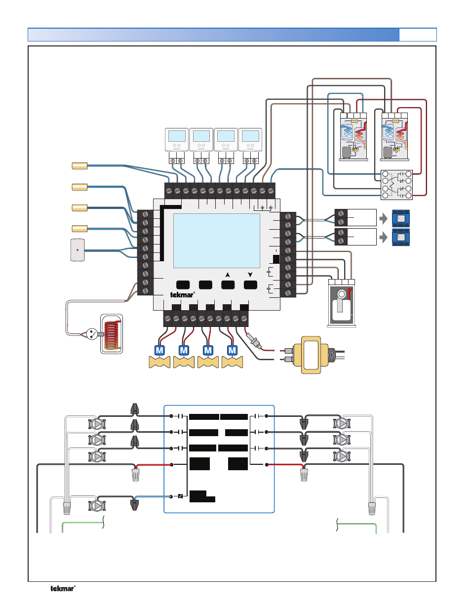
Electrical
A406-5
24 V (ac)
Transformer 009
Heat Pump Return
Sensor (S2)
Tank Sensor (S4)
tekmarNet
®
2 Thermostats
Outdoor
Sensor
(S1)
(P4)
(P6)
(Z1)
(Z2)
(Z3)
(Z4)
Boiler Sensor (S3)
DHW Call
(P3)
(P2)
Mod Con
Boiler
Two Water to Water Heat Pumps
(P1)
Mix Sensor (S5)
(P5)
(P7)
See page 40 for details on common modulating boiler settings.
003