N1 l1 g, N2 g l2, Nl l – tekmar 406 House Control Installation User Manual
Page 5
5 of 48
© 2012 406_D - 11/12
Power
Source 2
Mix System
Pump
DHW
Pump
Transfer
Pump
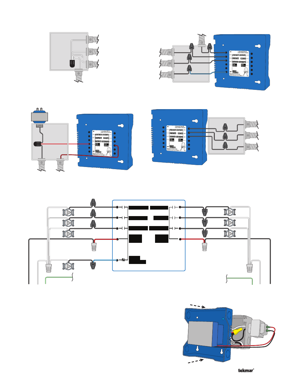
Figure 3 - Connect Neutral Wires
for Power Source 2
Figure 4 - Line Voltage
Power
Source 2
Power
Source 1
Figure 5 - System Pumps (Left)
Tank System Pump
HP Loop
Pump
Variable
Speed Pump
Boil System
Pump
Figure 6 - System Pumps (Right)
Mix System
Pump
DHW
Pump
Transfer
Pump
Ensure that the pump wires are neatly tucked inside the
electrical box.
Using 2 of the 4 holes in the back of the enclosure, securely
fasten it to the junction box extension ring with 2 #10 screws
as shown in Figure 7.
•
•
Install The Enclosure ----------------------------
----------------------------
Figure 7
Boil Sys
HP Sys
Mix Sys
DHW
Transfer
Variable
Speed
115 V (ac)
N1
L1
G
115 V (ac)
N2
G
L2
to pump grounds
to pump grounds
N
N
L
L
Tank Sys
Mix Sys Pump
Tank Sys Pump
DHW Pump
Transfer Pump
Boil Sys Pump
HP Loop Pump
Pump
Power (L)
Pump
Power (L)
Variable
Speed Pump
(blue)
(red)
(black)
(black)
(black)
(red)
(black)
(black)
(black)
Rear Line Voltage Wiring Diagram ----------------------------------------------------------------------
----------------------------------------------------------------------
Back of House Control 406