tekmar 406 House Control Installation User Manual
Page 40
©
2012 406_D
-
11/12
40
of
48
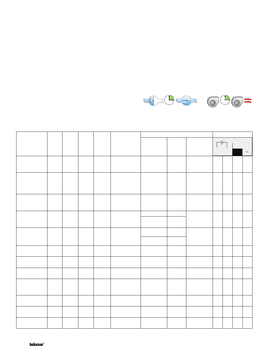
Boiler Model
BOIL
TYPE
BOIL
MOTR
(sec)
MIN
MOD
(%)
MOD
DELAY
(min)
Required
Equipment
from Boiler
Manufacturer
Boiler Control Setting
Wiring Terminals
+
Mod dc/mA
Backup
Parameter Setting Reference
Buderus
GB142, 162,
312
0-10
10
30
0:10
EM10 Module
None
None
None
2
1
Burnham
Alpine
4-20
30
0
0:10
None
Central
Heating
Modulation
Source
4-20mA
p.109 I&O
Manual
1
2
9
10
Dunkirk
Q95M-200
0-10
10
18
1:45
HAM 0-
10VDC
Module
Parameter
34 [P .34]
[- - 04]
p.3 Ham
Installation
Instructions
+
-
Heat Transfer
Products Elite
0-10
24
16
0:00
None
Function 16 0-10 Volt
p.57
Installation
Manual
+
_
Function 17
Fan
Speed
Heat Transfer
Products
Munchkin
0-10
60
16
0:00
Munchkin
Interface
Board
Function 16
1
p.60 Boiler
Manual
Pu
rp
le
Ye
llo
w
Function 17
1
Laars
NeoTherm
4-20
30
0
0:50
None
None
None
None
5
6
4
3
Lochinvar
Knight
0-10
16
20
0:10
None
H3
Active
p.24 Service
Manual
33
34
Lochinvar
Sync
0-10
16
20
0:10
None
Demand
conf
3
p.19 Service
Manual
19
20
Peerless
PureFire
REV2
0-10
50
20
0:00
Interface
Adapter PFA-
1
Heating
Mode
Mode 5
p.43 I&O
Manual
16
15
Triangle Tube
Prestige Solo
0-10
90
18
2:05
None
Parameter
45
02
p.54 I&M
Manual
17+ 18-
Weil-McLain
Ultra Series 3
0-10
60
20
0:30
None
ADD’L HEAT
DEMAND
Type 4
p.64 Boiler
Manual
6
5
Viessmann
Vitodens 100
EMS 2
N/A
N/A
N/A
Input Module
0-10V OT
None
None
None
1
4
For updated information or wiring details, check the service bulletin page on www.tekmarControls.com.
Essential Settings for House Control 406 with Common Modulating Boilers
--------------------------------
--------------------------------
Modulating Boiler Operation --------------------
--------------------
The 406 can operate a single hot-water modulating boiler
using the Mod dc/mA output and the Backup contact. Not all
boilers require the use of the Backup contact.
The control operates the boiler by first switching the Backup
contact to allow the modulating boiler to go through the ignition
sequence. A 0-10 V (dc) or 4-20 mA analog signal is then used
to modulate the boiler firing rate starting from 50% (5 V (dc)
or 12 mA signal) for 30 seconds.
After the 30 second delay has elapsed, the control will then
allow the boiler to modulate down to the minimum modulation
setting and hold it there for the MOD DELAY time.
After the MOD DELAY has elapsed, the control uses PID
logic to change the boiler firing rate signal in order to satisfy
the boiler target temperature. When the firing rate signal is
reduced down to the MIN MOD setting and the boiler supply
temperature exceeds the boiler target by 1/2 of the differential,
the control will shut off the burner.
Boiler Motor Speed ------------------------------
------------------------------
The Motor Speed is the amount of time the boiler requires to
go from 0% modulation to 100% modulation.
Gas valve actuating motors have a design time from fully
closed to fully opened which can be found in the manufacturer’s
manual. The Motor Speed should be set to this time.
The Motor Speed setting for a Variable Frequency Drive (VFD)
is the amount of time required to go from a stopped position
to 100% fan speed. Since a VFD has a very quick response
rate, it may be necessary to increase the Motor Speed setting
in order to increase the stability of the boiler modulation.
Use the BOIL MOTR setting in the Adjust Menu to select an
appropriate boiler motor speed.
OR