Control wiring, Sizing the transformer – tekmar 406 House Control Installation User Manual
Page 4
©
2012 406_D
-
11/12
4
of
48
HP Loop
Pump
Variable
Speed Pump
Boil System
Pump
Tank System Pump
Power
Source 1
Control Wiring
Line Voltage Wiring ------------------------------------------------------------------------------------
------------------------------------------------------------------------------------
Ensure Junction Box Extension Ring is Installed
An extension ring must be installed on the 4” x 4” junction
box when 6 or more powered outputs for the pumps are
used on the rear of the control.
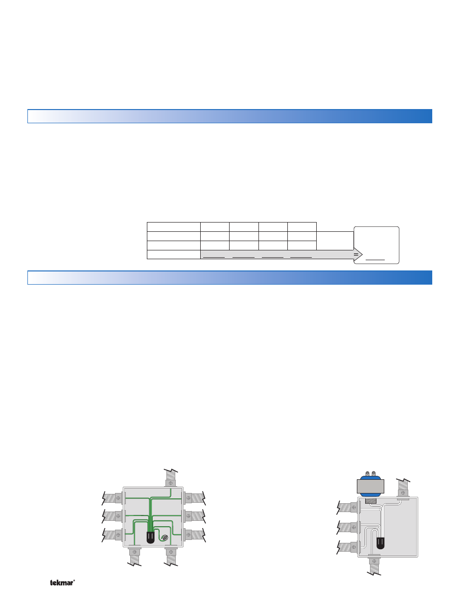
Ground the Pumps
Connect the pump grounds to the power supply ground as
shown in Figure 1. The ground wire must also be grounded
to the electrical box.
Wire the Pump Neutrals
If the combined pump power load is less than 12 A, then a
only a single 15 A circuit is required.
If the combined pump power load exceeds 12 A, then two
separate 15 A circuits are required.
Each power circuit requires it’s own neutral wire.
Connect the Neutral (N) wires from each pump and wire to
•
•
•
•
•
•
the 115 V (ac) Neutral (N) wire. If the transformer has been
mounted to this electrical box, connect its neutral wire with
this group. This is shown in Figure 2 and Figure 3.
Wire the Pump Power (L)
If the combined pump power load is less than 12 A, then a
only a single 15 A circuit is required.
If the combined pump power load exceeds 12 A, then two
separate 15 A circuits are required.
Connect the 115 V (ac) line voltage (L) wire to the red Pump
Power (L) wire on the back of the House Control and to the
115 V (ac) side of the transformer. Use a wire nut or approved
connector. See Figure 4.
Wire the Pumps
Wire each remaining line voltage pump wire into the push-in
wire connector of the corresponding pump lead on the back
of the House Control. This is shown in Figure 5 and 6.
•
•
•
•
CAUTION: TURN ALL POWER OFF BEFORE PERFORMING ANY WIRING.
HP Loop
Pump
Power
Source 1
Power
Source 2
Tank System Pump
Mix System P
DHW Pump
Transfer Pum
Variable
Speed Pump
Boil System
Pump
Figure 1 - Connect Ground Wires
Figure 2 - Connect Neutral Wires
for Power Source 1
Pull two conductor 18 AWG LVT cable, up to 500 feet
(150 m) for the following equipment:
tekmarNet
®
2 Thermostats
Heat Pump Compressor Stage 1
Heat Pump Compressor Stage 2 (if applicable)
Heat Pump Reversing Valve (O or B)
Modulating Boiler 0-10 V (dc) or 4-20 mA (if applicable)
On/Off Boiler or Backup Heat Source (if applicable)
•
•
•
•
•
•
Outdoor Temperature Sensor
HP Return Temperature Sensor
Tank Supply Temperature Sensor
Boiler Supply Temperature Sensor (if applicable)
Mix Supply Temperature Sensor (if applicable)
DHW Tank Temperature Sensor (if applicable)
DHW Tank Aquastat (if applicable)
Setpoint Device (if applicable)
•
•
•
•
•
•
•
•
The control requires an external transformer. A tekmar Transformer
009 (or 009K which includes a 4”x 4” electrical box) can
supply up to 40 VA, and includes an in-line fuse to protect the
transformer and control.
In order to correctly size the external transformer, all loads
connected to the control must be taken into account.
When adding up the loads, consider the following:
tekmarNet
®
2 Thermostats draw approximately 2 VA each.
Each zone valve must be sized for peak load. This can be
•
•
Sizing the Transformer
obtained by multiplying the peak current draw (in Amps) by
24 V (ac).
If using a Floating Action mixing valve, add the VA draw for
the actuating motor. A tekmar Actuating Motor 741 draws
1.5 VA during normal operation.
The total power capacity of the power supply should be larger
than the total load of all the devices connected to the control. This
total load must not exceed 100 VA. Multiple tekmar Transformer
009’s can be wired together to increase total VA capacity.
•
Zone
1
2
3
4
Thermostat Load
Control
Load (VA)
Zone Valve Load
Total Zone Load
2
Transformer
must exceed:
VA
+
+
+
+
This chart is provided to
simplify transformer sizing: