tekmar 374 Universal Reset Control User Manual
Page 21
21 of 36
© 2009 D 374 - 03/09
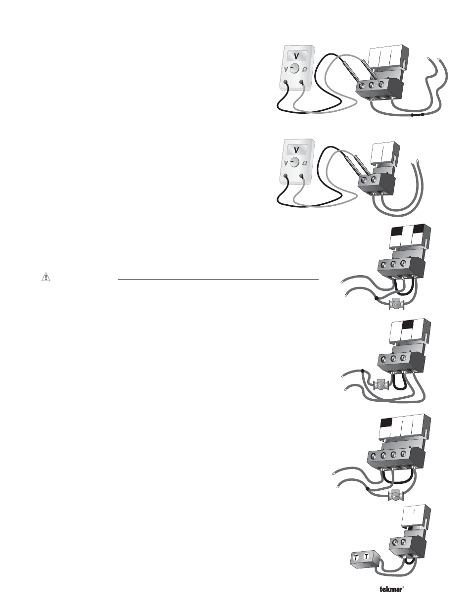
DHW Demand
If a DHW demand is used, measure the voltage between the
DHW Dem and the Com Dem terminals (29 and 31). When the DHW
demand device calls for heat, between 20 and 260 V (ac) should be
measured at the terminals. When the DHW demand device is off,
less than 5 V (ac) should be measured.
Setpoint Demand
If a setpoint demand is used, measure the voltage between the
Setp Dem and the Com Dem terminals (28 and 31). When the
setpoint demand device calls for heat, between 20 and 260 V (ac)
should be measured at the terminals. When the setpoint demand
device is off, less than 5 V (ac) should be measured.
Mix 1 Demand
If a mix 1 demand is used, measure the voltage between the
Mix1 Dem and the Com Dem terminals (25 and 26). When the mix 1
demand device calls for heat, between 20 and 260 V (ac) should be
measured at the terminals. When the mix 1 demand device is off,
less than 5 V (ac) should be measured.
Mix 2 Demand
If a mix 2 demand is used, measure the voltage between the
Mix2 Dem and the Com Dem terminals (27 and 26). When the mix 2
demand device calls for heat, between 20 and 260 V (ac) should be
measured at the terminals. When the mix 2 demand device is off,
less than 5 V (ac) should be measured.
Test the Outputs
Primary Pump (Prim P1)
If a primary pump is connected to the
Prim P1 terminal (16), make sure that power
to the terminal block is off and install a jumper between the
Power L and Prim P1
terminals (14 and 16). When power is applied to the
Power L and Power N terminals (14
and 15), the primary pump should start. If the pump does not turn on, check the wiring
between the terminal block and pump and refer to any installation or troubleshooting
information supplied with the pump. If the pump operates properly, disconnect the
power and remove the jumper.
Mix 1 Pump (Mix 1 P2)
If a mix 1 pump is connected to the
Mix1 P2 terminal (13), make sure that power to the
terminal block is off and install a jumper between the
Power L and Mix1 P2 terminals
(14 and 13). When power is applied to the
Power L and Power N terminals (14 and
15), the mix 1 pump should start. If the pump does not turn on, check the wiring
between the terminal block and pump and refer to any installation or troubleshooting
information supplied with the pump. If the pump operates properly, disconnect the
power and remove the jumper.
Mix 2 Pump (Mix 2 P3)
If a mix 2 pump is connected to the
Mix2 P3 terminal (17), make sure that power
to the terminal block is off and install a jumper between the
Power L and Mix2 P3
terminals (14 and 17). When power is applied to the
Power L and Power N terminals
(14 and 15), the mix 2 pump should start. If the pump does not turn on, check the wiring
between the terminal block and pump and refer to any installation or troubleshooting
information supplied with the pump. If the pump operates properly, disconnect the
power and remove the jumper.
Stage 1 / Boil Enable Contact
If an on / off boiler or a Lo fire boiler stage is connected to the
Stage 1 / Boil Enbl.
terminals (21 and 22), make sure power to the boiler circuit is off, and install a jumper
between the terminals. When the boiler circuit is powered up, the boiler should fire.
If the boiler does not turn on, refer to any installation or troubleshooting information
supplied with the boiler. (The boiler may have a flow switch that prevents firing until
the primary pump (
Prim P1) is running). If the boiler operates properly, disconnect the
power and remove the jumper.
30
Boil
Dem
Com
Dem
29
31
DHW
Dem
20 to 260 V (ac)
20 to 260 V (ac)
26
Com
Dem
25
Mix1
Dem
115 V (ac)
L
N
15
N
14
16
Prim
P1
L
Power
115 V (ac)
L
N
13
15
N
14
Mix1
P2
L
Power
16
17
Prim
P1
Mix2
P3
115 V (ac)
L
N
15
N
14
L
Power
22
21
Stage 1/
Boil Enbl.