tekmar 374 Universal Reset Control User Manual
Page 15
15 of 36
© 2009 D 374 - 03/09
MIXING TERMINAL UNITS
When a terminal unit is selected, the control automatically loads the mixing design temperature, mixing maximum supply temperature,
and mixing minimum supply temperature. The factory defaults are listed below. The factory defaults can be changed to better
match the installed system. If a factory default has been changed, refer to section A to reload the factory defaults.
Terminal Unit
High Mass
Radiant (1)
Low Mass
Radiant (2)
Fancoil
(3)
Fin-Tube
Convector (4)
Radiator
(5)
Baseboard
(6)
MIX DSGN
120°F (49°C)
140°F (60°C)
190°F (88°C)
180°F (82°C)
160°F (71°C)
150°F (66°C)
MIX MAX
140°F (60°C)
160°F (71°C)
210°F (99°C)
200°F (93°C)
180°F (82°C)
170°F (77°C)
MIX MIN
OFF
OFF
100°F (38°C)
OFF
OFF
OFF
MIX MODE 2 – MIXING SETPOINT OPERATION
Mixing device 2 can operate at a mixing setpoint temperature by setting Mix 2 Mode to 2. The Mix 2 Target temperature can then
be set to the desired temperature. While the boiler supply temperature is close to the boiler minimum temperature, the mix 1 device
has priority over the mix 2 device when set to Mix 2 Mode 2.
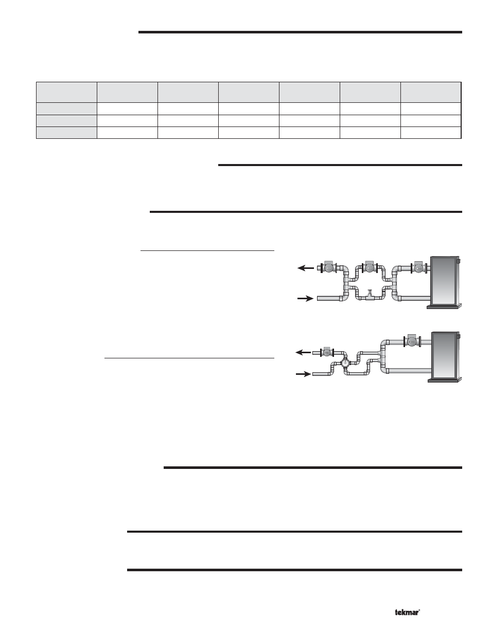
MIXING DEVICE SELECTION
The control can supply a lower water temperature to part of the heating system by varying the speed of an injection pump or
modulating a mixing valve. This selection is made using the
Floating / Variable DIP switch.
Variable Speed Injection
Standard wet rotor circulators are connected to the control on
Var1 terminal (2) for mix 1 demands and Var2 terminal (5) for mix 2
demands. The control increases or decreases the power output to
the circulator when there is mix demand. The circulator speed varies
to maintain the correct mixed supply water temperature at the mix
supply sensor. For correct sizing and piping of the variable speed
injection driven circulator, refer to essay E 021. A visual indication of
the current variable speed output is displayed in the LCD in the form of
a segmented bar graph. There are separate bar graphs for each mix 1
and mix 2 outputs as indicated by a 1 or a 2 next to the bar graph.
Floating Action
Floating action actuator motors are connected to the control on the
Opn
and
Cls terminals. Mix 1 has Opn and Cls terminals (1 and 2) and Mix 2
has separate
Opn and Cls terminals (4 and 5). Power for both floating
action actuator motors are shared on the
Pwr Mix terminal (3).
The control pulses the actuator motor open or close to maintain the correct supply water temperature at the mix supply sensor
when there is a mix demand. The mixing valve that the actuator is connected to can be either a 2-way, 3-way or 4-way valve. A
visual indication as to whether the control is currently opening or closing the mixing valve is displayed in the LCD with the words
Open and Close while viewing the Mix Supply and Mix Target temperatures. Also, a visual indication of the current position of
the valve is displayed in the LCD in the form of a segmented bar graph. There are separate bar graphs for each mix 1 and mix 2
outputs as indicated by a 1 or a 2 next to the bar graph.
BOILER MINIMUM PROTECTION
The control is capable of providing boiler protection from cold mixing system return water temperatures. If the boiler water temperature
is cooler than the Boiler Minimum setting while the boiler is firing, the control reduces the output from the mixing devices. If mix2
is operating in setpoint mode 2, it is the first to reduce its output. Otherwise, both outputs are reduced at the same rate. Reducing
the mixing output limits the amount of cool return water to the boiler and allows the boiler water temperature to recover. This feature
can only be used if the boiler sensor is on the supply or on the return.
MIX 1 PUMP CONTACT
If the control receives a
Mix 1 Demand and is not in WWSD, the control closes the Mix1 P2 pump contact and the mixing pump 2
segment is displayed in the LCD.
MIX 2 PUMP CONTACT
If the control receives a
Mix 2 Demand and is not in WWSD, the control closes the Mix2 P3 pump contact and the mixing pump 3
segment is displayed in the LCD.