tekmar 374 Universal Reset Control User Manual
Page 18
© 2009 D 374 - 03/09
18 of 36
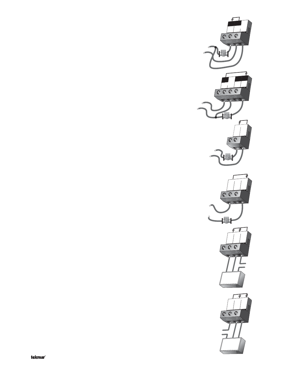
Mix 1 System Pump (Mix1 P2)
The
Mix1 P2 output terminal (13) is a powered output. When the relay in the control
closes, 115 V (ac) is provided to the
Mix1 P2 terminal (13) from the Power L terminal (14).
To operate the mix 1 pump, connect one side of the mix 1 pump circuit to terminal 13
and the second side of the pump circuit to the neutral (
Power N) side of the 115 V (ac)
power supply.
Mix 2 System Pump (Mix2 P3)
The
Mix2 P3 output terminal (17) is a powered output. When the relay in the
control closes, 115 V (ac) is provided to the
Mix2 P3 terminal (17) from the Power L
terminal (14). To operate the mix 2 pump, connect one side of the mix 2 pump circuit
to terminal 17 and the second side of the pump circuit to the neutral (
Power N) side of
the 115 V (ac) power supply.
Variable Speed Injection Pump
The control can vary the speed of a permanent capacitor, impedance protected or
equivalent pump motor that has a locked rotor current of less than 2.4 A. Most small
wet rotor circulators are suitable as described in Essay E 021. The control has an
internal overload fuse that is rated at 2.5 A 250 V (ac) for each variable speed output.
Contact your tekmar sales representative for details on the repair procedures if the
fuse(s) is blown.
Mix 1
Connect one of the wires from the variable speed injection pump to the
Cls Var1
terminal (2) on the control. Connect the
Pwr Mix terminal (3) to the live (L) side of
the 115 V (ac) power source. The other wire on the variable speed injection pump
must be connected to the neutral (N) side of the 115 V (ac) power supply.
Mix 2
Connect one of the wires from the variable speed injection pump to the
Cls Var2
terminal (5) on the control. Connect the
Pwr Mix terminal (3) to the live (L) side of
the 115 V (ac) power source. The other wire on the variable speed injection pump
must be connected to the neutral (N) side of the 115 V (ac) power supply.
Mixing Valve Actuator
Mix
1
Connect one side of the 24 V (ac) power to the
Pwr Mix terminal (3) on the control.
The output relay
Opn 1 (1) is then connected to the open terminal of the actuating
motor and the output relay
Cls Var1 (2) is connected to the close terminal of the
actuating motor. Connect the second side of the 24 V (ac) circuit to the common
terminal of the actuating motor.
Caution: The same 24 V (ac) transformer must be used to power the mix 1 and the
mix 2 floating action actuating motors.
Mix 2
Connect one side of the 24 V (ac) power to the
Pwr Mix terminal (3) on the control.
The output relay
Opn (4) is then connected to the open terminal of the actuating
motor and the output relay
Cls Var2 (5) is connected to the close terminal of the
actuating motor. Connect the second side of the 24 V (ac) circuit to the common
terminal of the actuating motor.
Caution: The same 24 V (ac) transformer must be used to power the mix 1 and the
mix 2 floating action actuating motors.
13
L
15
14
Mix1
P2
Power
N
115 V (ac)
N
L
15
L
N
16
Prim
P1
17
Mix2
P3
14
Power
115 V (ac)
L
N
2
Cls1
Var1
3
Pwr
Mix
115 V (ac)
N
L
3
4
5
Cls
Var2
Pwr
Mix
Opn
2
N
L
115 V (ac)
1 2 3
Pwr
Mix
Opn
1
Cls1
Var1
C
R
24 to 230 V (ac)
Opn
Cls
Actuating Motor
Com
3 4 5
Cls
Var2
Pwr
Mix
Opn
2
C
R
24 to 230 V (ac)
Com
Opn Cls
Actuating Motor