tekmar 374 Universal Reset Control User Manual
Page 19
19 of 36
© 2009 D 374 - 03/09
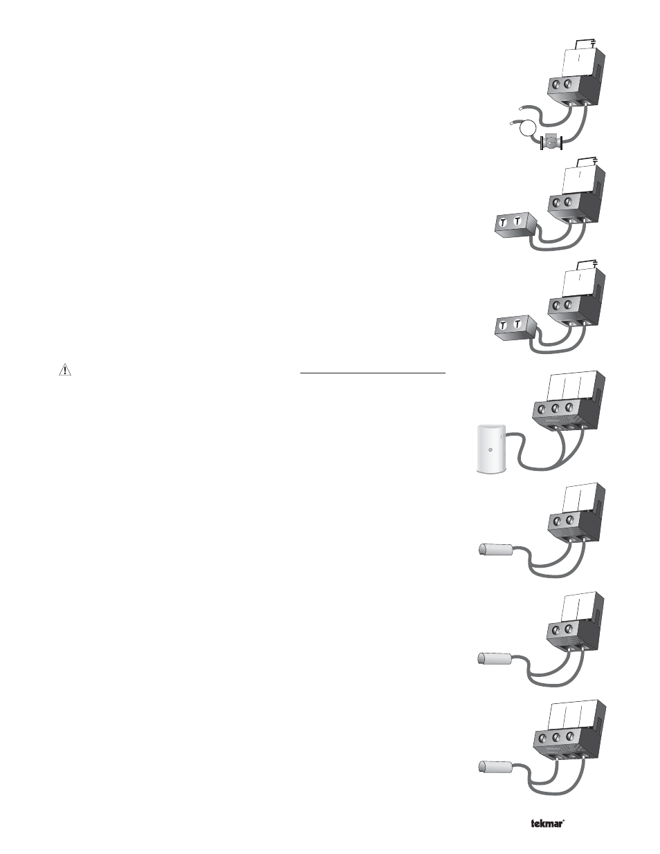
DHW Pmp / Vlv Contact
The
DHW Pmp / Vlv terminals (19 and 20) are an isolated output. There is no power
available on these terminals from the control. These terminals are to be used as a
switch to either make or break power to the DHW pump or the DHW valve. Since this
is an isolated contact, it may switch a voltage between 24 V (ac) and 230 V (ac).
Stage 1 / Boil Enable Contact
The
Stage 1 / Boil Enbl. terminals (21 and 22) are isolated outputs in the control.
There is no power available on these terminals from the control. These terminals are
to be used as a switch to either make or break power to a boiler or a Lo fire stage
on a single boiler. Since this is an isolated contact, it may switch a voltage between
24 V (ac) and 230 V (ac).
Stage 2 / Setp Enable Contact
The
Stage 2 / Setp Enbl. terminal (23 and 24) are isolated output in the control. There
is no power available on these terminals from the control. These terminals are to be
used as a switch to either make or break power to a boiler or a Hi fire stage on a single
boiler. In the case where the boiler sensor is connected to the return or there is no
boiler sensor installed, these terminals are used to provide a setpoint demand to the
boiler’s control if applicable. Since this is an isolated contact, it may switch a voltage
between 24 V (ac) and 230 V (ac).
Sensor and Unpowered Input Connections
Do not apply power to these terminals as this will damage the control.
Outdoor Sensor
Connect the two wires from the Outdoor Sensor 070 to the
Com and Out terminals
(7 and 9). The outdoor sensor is used by the control to measure the outdoor air
temperature.
Boiler Sensor
Connect the two wires from the Boiler Sensor 082 to the
Com and Boil terminals
(7 and 8). When the
Return / Supply DIP switch is set to Supply, the boiler sensor
is used by the control to measure the boiler supply water temperature. When the
Return / Supply DIP switch is set to Return, the boiler sensor is used by the control to
measure boiler return water temperature to provide boiler return protection.
Mix1 Sensor
Connect the two wires from the Mix1 Sensor 082 to the
Com and Mix1
terminals (10 and 11). The Mix1 sensor is used by the control to measure the mix 1
system temperature.
Mix2 Sensor
Connect the two wires from the Mix2 Sensor 082 to the
Com and Mix2
terminals (10 and 12). The Mix2 sensor is used by the control to measure the mix 2
system temperature.
19 20
M
24 to 230 V (ac)
DHW
Pmp/Vlv
or
Stage 1/
Boil Enbl.
22
21
Boiler
Stage 2/
Setp Enbl.
24
23
Boiler
7
Com
8
Boil
9
Out
8
Boil
7
Com
11
Mix1
10
Com
10
Com
11
Mix1
12
Mix2