Monitor menus – tekmar 262 Boiler Control Installation User Manual
Page 29
29 of 36
Copyright © D 262 -
12/08
Sketch the piping of the system. This is a relatively simple step that tends to be overlooked,
however it can often save hours of time in troubleshooting a system. Note flow directions in the
system paying close attention to the location of pumps, check valves, pressure bypass valves
and mixing valves. Ensure correct flow direction on all pumps. This is also a very useful step if
additional assistance is required.
Document the control for future reference. Before making any adjustments to the control, note
down all of the items that the control is currently displaying. This includes items such as error
messages, current temperatures and settings, and which devices should be operating as
indicated by the LCD. This information is an essential step if additional assistance is required
to diagnose the problem.
Isolate the problem between the control and the system. Now that the sequence of operation is
known and the system is sketched, is the control operating the proper pumps and valves at the
correct times? Is the control receiving the correct signals from the system as to when it should
be operating? Are the proper items selected in the menus of the control for the device that is to
be operated?
Test the contacts, voltages and sensors. Using a multimeter, ensure that the control is receiving
adequate voltage to the power terminals and the demand terminals as noted in the technical
data. Use the multimeter to determine if the internal contacts on the control are opening and
closing correctly. Follow the instructions in the Testing the Wiring section to simulate closed
contacts on the terminal blocks as required. Test the sensors and their wiring as described in
the sensor Data Brochures.
Monitor the system over a period of time. Select the applicable items in the Monitor menu of
the control and reset them to zero. Allow the system and the control to operate over a known
period of time and then record the Monitor items. Use this information to help diagnose any
remaining problems.
Sketch the
Piping in the
System
Document the
Control
Isolate the
Problem
Test the Contacts
Voltages &
Sensors
Monitor the
System
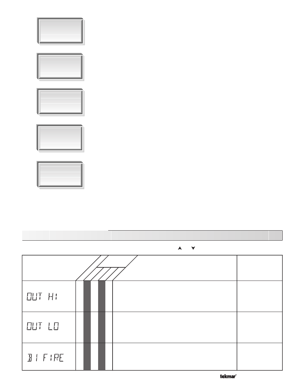
The highest recorded outdoor air temperature since this item
was last cleared. This can be used to diagnose if the Outdoor
Sensor 070 has been located correctly. If this reading is too
high, the 070 may be located in an area that receives direct
sunlight or is influenced by an exhaust vent. MODE = —1—
The lowest recorded outdoor air temperature since this item
was last cleared. This can be used to diagnose if the Outdoor
Sensor 070 has been located correctly. If this reading is too
high, there may not be adequate insulation behind the 070, or
there may be an exhaust vent nearby. MODE = —1—
The total number of running hours for Stage 1 since this item
was last cleared. This total time does not include the FIRE DLY
time set in the Adjust menu.
-67 to 149˚F
(-55 to 65˚C)
-67 to 149˚F
(-55 to 65˚C)
0 - 9999 hr
Section
262 Monitor Menu (1 of 3)
•
•
•
•
•
•
•
•
•
•
LT
D
USER INST ADV
Range
Access
Level
Description
Item Field
Note: To clear the recorded information in the specific Item field, press and hold and .