tekmar 262 Boiler Control Installation User Manual
Page 17
17 of 36
Copyright © D 262 -
12/08
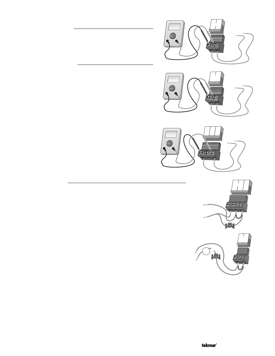
Test the Power Supply
Make sure exposed wires and bare terminals are not in contact with other
wires or grounded surfaces. Turn on the power and measure the voltage
between the N and L terminals (6 and 7) using an AC voltmeter, the
reading should be between 108 and 132 V (ac).
Test the Powered Inputs
Boiler Demand
If a
Boiler Demand is used, measure the voltage between the Boiler
Demand terminals (1 and 2). When the Boiler Demand device calls for
heat, you should measure between 20 and 260 V (ac) at the terminals.
When the
Boiler Demand device is off, you should measure less than
5 V (ac).
DHW Demand
If a
DHW Demand is used, measure the voltage between the DHW
Dem and the Com Dem terminals (3 and 4). When the DHW Demand
device calls for heat, you should measure between 20 and 260 V (ac)
at the terminals. When the
DHW Demand device is off, you should
measure less than 5 V (ac).
Setpoint Demand
If a
Setpoint Demand is used, measure the voltage between the Setp
Dem and the Com Dem terminals (3 and 5). When the Setpoint
Demand device calls for heat, you should measure between 20 and
260 V (ac) at the terminals. When the
Setpoint Demand device is off,
you should measure less than 5 V (ac).
Testing the Outputs
Boiler Pump (Boil P1)
If a boiler pump is connected to the
Boil P1 terminal (8), make sure that power to the
terminal block is off and install a jumper between the
Power L and the Boil P1 terminals
(7 and 8). When power is applied to the
Power N and Power L terminals (6 and 7), the
boiler pump should start. If the pump does not turn on, check the wiring between the
terminal block and pump and refer to any installation or troubleshooting information
supplied with the pump. If the pump operates properly, disconnect the power and remove
the jumper.
DHW Pump OR Valve (DHW Pmp/Vlv)
If a DHW pump or DHW valve is connected to the
DHW Pmp / Vlv terminals (9 and 10),
make sure the power to the pump or valve circuit is off and install a jumper between those
terminals. When the DHW circuit is powered up, the DHW pump should turn on or the
DHW valve should open completely. If the DHW pump or valve fails to operate, check the
wiring between the terminals and the pump or valve and refer to any installation or
troubleshooting information supplied with these devices. If the DHW pump or valve
operates correctly, disconnect the power and remove the jumper.
Stage 1 and 2
If the boiler is connected to the
Stage 1 terminals (11 and 12) and/or Stage 2 terminals (13 and 14), make sure power to the boiler
circuit is off and install a jumper between the terminals. When the boiler circuit is powered up, the boiler should fire. If the boiler does
not turn on, refer to any installation or troubleshooting information supplied with the boiler. (The boiler may have a flow switch that
prevents firing until the boiler pump (P1) is running.) If the boiler operates properly, disconnect the power and remove the jumper.
Ω
V
V
6
7
N
L
Power
108 to 132 V (ac)
Ω
V
20 to 260 V (ac)
V
1
2
Boiler
Demand
Ω
V
20 to 260 V (ac)
V
3
4
DHW
Dem
5
Setp
Dem
Com
Dem
120 V (ac)
7
8
L
P1
Boil
L
N
6
N
Power
24 to 240 V (ac)
9
10
DHW
Pmp/Vlv
M
or