Boiler demand, Dhw demand, Setpoint demand – tekmar 262 Boiler Control Installation User Manual
Page 15: Output connections boiler pump contact (boil p1), Dhw pump / valve contact, Boiler contacts, Sensor and unpowered input connections, Outdoor sensor, Boiler sensor
15 of 36
Copyright © D 262 -
12/08
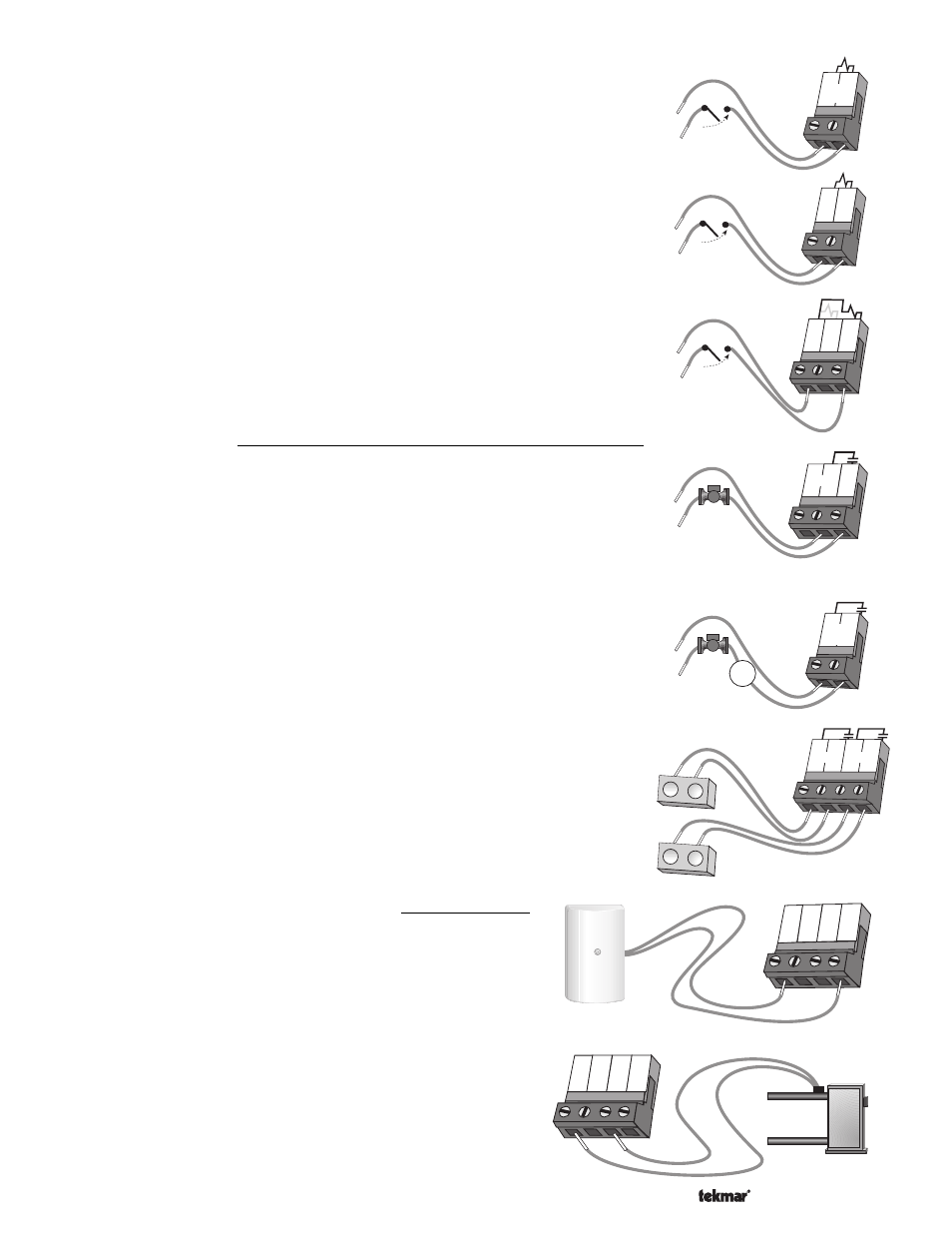
Boiler Demand
To generate a Boiler Demand, a voltage between 24 V (ac) and 240 V (ac) must be
applied across the
Boiler Demand terminals (1 and 2).
DHW Demand
To generate a DHW Demand, a voltage between 24 V (ac) and 240 V (ac) must be applied
across the
Com Dem and the DHW Dem terminals (3 and 4).
Setpoint Demand
To generate a Setpoint Demand, a voltage between 24 V (ac) and 240 V (ac) must be
applied across the
Com Dem and the Setp Dem terminals (3 and 5).
Caution: The same power supply must be used for both the DHW demand and setpoint
demand circuits since they share the
Com Dem terminals.
Output Connections
Boiler Pump Contact (Boil P1)
The boiler pump output terminal (8) on the 262 is a powered output. When the relay
contact in the 262 closes, 120 V (ac) line (L) is provided to the
Boil P1 terminal (8) from
the
Power L terminal (7). To operate the boiler pump, connect one side of the boiler pump
circuit to terminal 8 and the second side of the pump circuit to the neutral (N) side of the
120 V (ac) power supply.
DHW Pump / Valve Contact
The
DHW Pump / Valve terminals (9 and 10) are an isolated output in the 262. There is
no power available on these terminals from the control. These terminals are to be used
as a switch to either make or break power to the DHW pump or the DHW valve. Since
this is an isolated contact, it may switch a voltage between 24 V (ac) and 240 V (ac).
Boiler Contacts
The
Stage 1 and Stage 2 terminals (11, 12 and 13, 14) are isolated outputs in the 262.
There is no power available on these terminals from the control. These terminals are to
be used as a switch to either make or break the boiler circuit. When the 262 requires the
boiler(s) to fire, it closes the contact between terminals 11 and 12 and/or 13 and 14.
Sensor and Unpowered Input Connections
Do not apply power to these terminals as this damages the control.
Outdoor Sensor
Connect the two wires from the Outdoor Sensor 070 to the
Com and
Out terminals (19 and 22). The Outdoor Sensor is used by the 262 to
measure the outdoor air temperature.
Boiler Sensor
Connect the two wires from the Boiler Sensor 071 to the
Com and Boil
terminals (19 and 21). The Boiler Sensor is used by the 262 to
measure the supply (outlet) water temperature from the boiler(s).
1
2
24 to 240 V (ac)
Boiler
Demand
3
4
Com
Dem
DHW
Dem
24 to 240 V (ac)
3
4
Com
Dem
DHW
Dem
Setp
Dem
5
24 to 240 V (ac)
N
L
Boil
P1
8
7
6
Power
120 V (ac)
L
N
9
10
DHW
Pmp/Vlv
24 to 240 V (ac)
M
or
11 12
Stage
13 14
1
1
Stage
2
2
T
T
T
T
T
T
T
T
19
20
Com
DHW Boil
21
22
Out
19
20
Com
DHW
Boil
21
22
Out
Boiler
sensor