Testing the wiring, Pg 16, Dhw sensor – tekmar 262 Boiler Control Installation User Manual
Page 16: 10k sensor, Zone control input, Tekmar net, Device (tn1 / tn2), Unoccupied switch, Step five testing the wiring, Test the sensors
16 of 36
Copyright © D 262 -
12/08
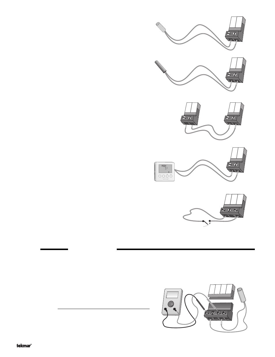
DHW Sensor
Connect the two wires from the DHW Sensor 071 to the
Com and DHW
terminals (19 and 20). The DHW Sensor is used by the 262 to measure
the DHW tank temperature.
10K Sensor
Either an Indoor Sensor, Slab Sensor, or Zone Control may be
connected to the
10K input. If a sensor is used, connect the two wires
from the sensor to the
Com and 10K terminals (16 and 17).
Zone Control Input
If an external tekmar Zone Control is used, connect the wire from the
Com Sen terminal on the Zone Control to the Com terminal (16) on the
262. Connect the
Zo Out terminal on the Zone Control to the 10K
terminal (17) on the 262.
Note: The wires from the Zone Control are polarity sensitive. The
communication does not operate correctly if the wires are reversed.
tekmar Net
TM
Device (tN1 / tN2)
A Room Temperature Unit (RTU) 062 or 063, or a Remote Display
Module (RDM) 040 may be connected to the
tekmar Net
TM
tN1 / tN2
input. Connect the
Com terminal from the appropriate device to the
Com terminal (16) on the 262. Connect the tekmar Net
TM
tN1 or tN2
terminal from the appropriate device to the
tekmar Net
TM
tN1 / tN2
terminal (15) on the 262.
Note: The wires from the RTU and the RDM are polarity sensitive. The
tekmar Net
TM
tN1 / tN2 device does not operate correctly if the wires
are reversed.
UnOccupied Switch
If an external timer (tekmar Timer 03
2) or switch is used, connect the
two wires from the external switch to the
Com and UnO Sw terminals
(16 and 18). When these two terminals are shorted together, the
control registers an UnOccupied signal.
Note: The setback override in the schedule menu of the control
overrides any external signal that is present at the UnOccupied Switch
terminals.
STEP FIVE
TESTING THE WIRING
Each terminal block
must be unplugged from its header on the control before power is applied for testing. To remove the terminal block,
pull straight down from the control.
The following tests are to be performed using standard testing practices and procedures and should only be carried out by properly
trained and experienced persons.
A good quality electrical test meter, capable of reading from at least 0 - 300
V (ac) and at least 0 - 2,000,000 Ohms, is essential to properly test the
wiring and sensors.
Test the Sensors
In order to test the sensors, the actual temperature at each sensor
location must be measured. A good quality digital thermometer with a
surface temperature probe is recommended for ease of use and accuracy.
Where a digital thermometer is not available, a spare sensor can be
strapped alongside the one to be tested and the readings compared. Test
the sensors according to the instructions in the Data Brochure D 070.
19
20
Com DHW
16
17
Com 10K
15
16
tN1 /
tN2
Com
Item
Menu
UnOcc 1
°F
View
Heat
Com
Sen
Zo
Out
tekmar 262
Zone Control
16
17
10K
Com
16
17
Com
10K
UnO
Sw
18
Timer Switch
Ω
Ω
V
19
20
Com
DHW
Boil
21
22
Out