Powers ES150 Emergency Tempering Valves with Dual Internal Cold Water By-Pass User Manual
Technical instructions, Hydroguard
TECHNICAL INSTRUCTIONS
HydroGuard
®
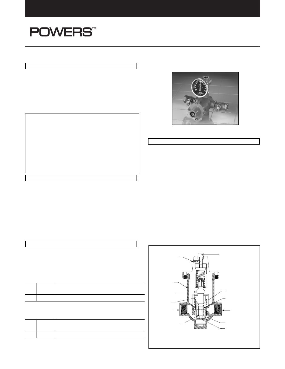
ES Series Emergency Tempering Valves
with Dual Internal Cold Water By-Pass
Model ES150
The Series ES HydroGuard thermostatically blends hot and cold
water to deliver tepid water to emergency fixtures, quickly
compensating for temperature variations due to changes in inlet
temperature or pressure. Powers’ exclusive Dual Internal
By-Pass* ensures cold water flow in the event of a valve failure or
loss of hot water.
* US Patent 6,575,377
Operating
Maximum Pressure . . . . . . . . . . . . . . . . . . . . . . . 125 psi (861.25 kPa)
Maximum Hot Water Temperature. . . . . . . . . . . . . . . . . 180°F (82° C)
Approach Temperature. . . . . . . . . . . . . . . . . . . . . . . . . . . . 15°F (8° C)
Temperature Adjustment Range . . . . . . 60° F (15° C) - 95° F (35° C)
Factory Set Temperature . . . . . . . . . . . . . . . . . . . . . . . 85°F (29° C)
Compliance. . . . . . . . . . . . . . . . . . . . . . . . . . . . . ANSI Z358.1 1998
Note: Set point cannot be less than the cold water temperature. For best opera-
tion, hot and cold water should be at least 15
°
F (8
°
C) from desired set point.
WARNING: TO ENSURE THE ACCURATE AND RELIABLE
OPERATION OF THIS PRODUCT, IT IS ESSENTIAL TO:
• Properly size each valve based on the individual application.
• Properly design the recirculation system to minimize pressure
and temperature variations.
• Conduct an weekly maintenance program to ensure proper
operation of all critical components.
FAILURE TO COMPLY WITH PROPER INSTALLATION
INSTRUCTIONS COULD CONTRIBUTE TO VALVE FAILURE,
RESULTING IN INJURY OR DEATH.
Typical Flow
Hot and cold water supplies enter HydroGuard at indicated ports,
(see Figure 3) then flow past their respective plug and seats. Next,
hot and cold water flow is directed to the mixing chamber where
the thermostatic actuator is located.
Temperature adjustment screw moves the actuator to determine
the discharge temperature.
With a rise in discharge temperature due to pressure or temperature
fluctuation on the inlet, the actuator expands, decreasing flow of hot
water. The reverse occurs with a drop in discharge temperature.
• Cold water supply failure – causes actuator to expand allowing
the motor to close the hot water seat.
• Hot water supply pressure failure – causes actuator to contract
opening cold water bypass ports. Secondary bypass mecha-
nism opens upon failure of actuator or hot water.
Model ES150
Table 1, Capacity Tables, present the HydroGuard discharge
capacity in gpm and Ipm for various pressure differentials (the
difference between the lowest inlet pressure and the discharge
pressure at the HydroGuard).
Table 1- Capacity Tables
Flow Capacity in US gpm at 50-50 Mixed Ratio
Model Min. Flow
Pressure Drop Across Valves in psi
Rate 5
10
20
30
40
45
60
75
ES150
1.0 gpm
4
6
9
14
16
17
20
23
Flow Capacity in lpm at 50-50 Mixed Ratio
Model Min. Flow
Pressure Drop Across Valves in kP
A
Rate 34
69
138
207
310
414
517
ES150
2.7 lpm
15.2
22.7
34.1
53.0
64.4
75.8
87.1
NOTE: By-Pass flows will vary based on inlet supply conditions including
water pressure and cold water temperature.
Body
Cold Water
Mixing Chamber
Secondary
By-Pass Spring
Primary By-Pass
Secondary By-Pass
Temperature
Adjustment
Screw
Adjustment
Locking
Screw
Thermostatic
Actuator
Hot Water
Hot/Cold
Water Shuttle
Return Spring/Primary
By-Pass Spring
Figure 3
Form TI ES150 v3
DESCRIPTION
OPERATION
SPECIFICATIONS
SIZING