Powers e430 Series Master Mixing Valves User Manual
Page 3
TI430 v3
Page 3
PART DESCRIPTION
REPAIR KIT INCLUDES:
431 Part No.
432 Part No.
433 Part No.
434 Part No.
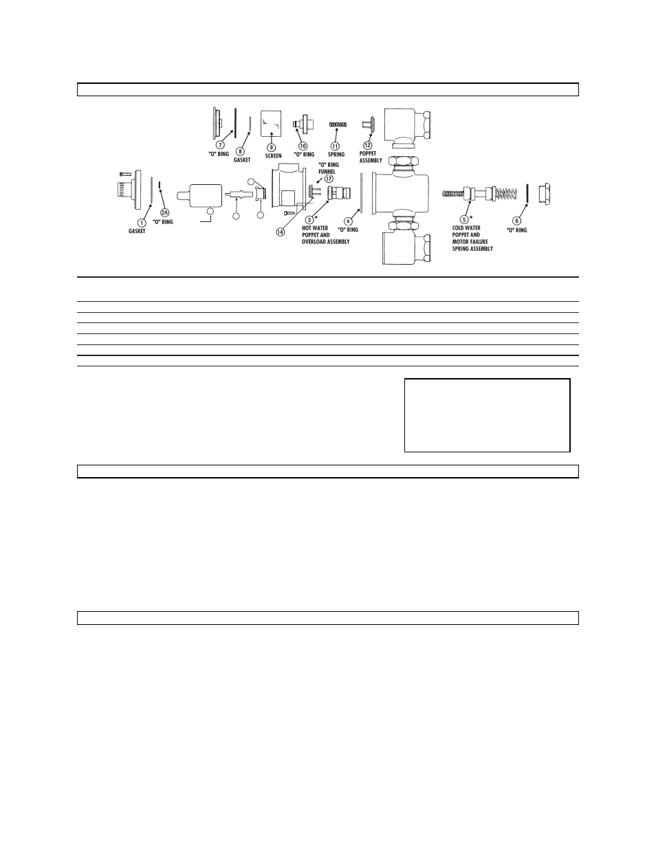
(Numbers below correspond with numbers in Figure 2)
Thermal Actuator
1,2, 4, 13, 15
390-037
390-036
390-065
390-066
Strainer Replacement
7, 8, 9, and 10
230-134
230-134
230-136
230-136
Checkstop Replacement
7, 8, 10, 11, and 12
230-135
230-135
230-137
230-137
Gasket and Disc Replacement
1, 2A, 4, 6, 7, 8, 10, and 12
390-294
390-298
390-302
390-306
Mixing Valve Replacement
3, 4, 5, and 6
390-067
390-068
390-069
390-070
Upgrade Kits for Older Valves**
1, 2, 2A, 4, 13, 14, 15,16, 17
390-016
390-017
390-511
390-512
Strainer and Checkstop Repair Kits contain parts for one (1) pair.
Repair Kits containing “O” Rings include silicone gel for use on “O” Rings during installation.
** For valves shipped prior to 1-1-2001.
REPAIR KITS (Repair Kit Parts)
What to look for if:
• The flow of water is less than desired.
a. Stop valves or supply to Hydroguard not fully open.
b. Clogged checkstop strainer screens.
c. Accumulation of lime deposits around valve seats.
d. Low supply pressures or unusual supply temperatures.
• The flow of water is completely shut off.
a. Stop valves or supply valves are completely closed.
b. Valves downstream from Hydroguard fully closed.
c. Loss of either hot or cold water supply pressure.
• Discharge temperature varies:
a. Very large restriction in outlet flow.
b. Very large drop in inlet pressure.
c. Very large fluctuation of hot water supply temperature.
d. Worn valve seats.
e. Minimum flow requirement not achieved.
MAINTENANCE AND TROUBLESHOOTING
1. IMPORTANT: Flush all piping thoroughly before installing.
2. Valve should be installed close to the hot water supply and
should easily be adjusted and repaired.
3. Remove body screws to turn outlet to any of four positions.
The Hydroguard body can be rotated to any position due to
the union inlets. Note: Make certain the body screws and
unions are tightened securely to prevent leakage.
4. CAUTION: When the Hydroguard supplies tempered water
to self-closing and/or solenoid valves, provide a shock
absorber (Powers Part No. 460-353) on the discharge line.
This protects the Hydroguard thermostatic motor from dam-
age by water shock waves generated by the quick closing
valves.
5. Before use, check maximum discharge temperature.
Reset if necessary.
OPERATION CHECK:
After Hydroguard is installed, make certain the supply stop
valves and strainers are free and clean and ready for operation
by disassembling checkstops as shown in "Servicing", steps 1,
2, and 3.
INSTALLATION INSTRUCTIONS
OVERLOAD
ASSEMBLY
ACTUATOR
STEM
ADAPTER
2
16
"O" RING
15
13
Figure 2
CALIFORNIA PROPOSITION 65 WARNING
WARNING: This product contains chemicals
known to the State of California to cause cancer
and birth defects or other reproductive harm.
(Installer: California law requires that this warning
be given to the consumer.)
For more information: www.wattind.com/prop65