Powers e430 Series Master Mixing Valves User Manual
Technical instructions
The Series 430 Hydroguard thermostatically blends hot and
cold water to deliver mixed water at the desired temperature,
compensating for temperature, pressure, and flow changes in
the supply lines, and reduces flow upon water supply failure.
The delivery is adjustable between 40°F and 160°F (4-71°C).
Maximum Pressure Differential . . . . . . . . . . . . .100 psi (689 kPa)
Maximum Static Pressure . . . . . . . . . . . . . .125 psig (861.25 kPa)
Maximum Hot Water Temperature . . . . . . . . . . . . . .200°F (93°C)
Minimum Hot Water Supply Temp . .15°F (8°C) Above Set-Point
Temperature Adjustment Ranges* . . . . . . . . .40°-160°F (4°-71°C)
Listing . . . . . . . . . . . . . . . . . . . . . . . . . . . . . . . . . . . . . .ASSE 1017
Certified . . . . . . . . . . . . . . . . . . . . . . . . . . . . . . . . . . . . .CSA B125
* Note: Low limit cannot be less than the cold water temperature. For best
operation, hot water should be at least 15°F (8°C) above desired set point.
TECHNICAL INSTRUCTIONS
431/432/433/434 Hydroguard
Master Mixing Valves
A Watts Industries Co.
DESCRIPTION
SIZING
SPECIFICATIONS
Table 1- Flow Capacity in US gpm at 50-50 Mixed Ratio
Model Min Flow Min Flow
Pressure Drop Across Valves in psi
Rate* to ASSE 1017
5
10
20
30
45
60
75 100
431
0.5 gpm
4.0 gpm
7.5
11
16
20
25
29
33 38.5
432
0.5 gpm
7.0 gpm
15
20
30
36
45
52
58
67
433
0.5 gpm
10.0 gpm
24
35
51
64
80
93 105 123
434
0.5 gpm
15.0 gpm
40
55
82
101 125 146 165 190
* Minimum flow when Hydroguard is installed at or near hot water source with recirculated tempered water with
continuously operating recirculating pump.
Flow Capacity in lpm at 50-50 Mixed Ratio
Model Min Flow Min Flow
Pressure Drop Across Valves in kP
A
Rate*
to ASSE 1017
34
69
138
207
310 414
517 689
431
1.89 lpm
15 lpm
28.4
41.6
60.6
76.0
94.6 109.8 125.0 145.7
432
1.89 lpm
26 lpm
56.8
76.0 113.5 136.2 170.3 197.0 219.5 253.5
433
1.89 lpm
38 lpm
1.5
2.2
3.2
4.0
5.0
5.9
6.6
7.8
434
1.89 lpm
57 lpm
2.5
3.5
5.2
6.4
7.9
9.2
10.0
12.
* Minimum flow when Hydroguard is installed at or near hot water source with recirculated tempered water with
continuously operating recirculating pump.
WARNING: TO INSURE THE ACCURATE AND RELIABLE
OPERATION OF THIS PRODUCT, IT IS ESSENTIAL TO:
• Properly size each valve based on the individual application
• Properly design the recirculation system to minimize pressure
and temperature variations
• Conduct an annual maintenance program to insure proper
operation of all critical components
FAILURE TO COMPLY WITH PROPER INSTALLATION
INSTRUCTIONS COULD CONTRIBUTE TO VALVE FAILURE,
RESULTING IN INJURY OR DEATH.
Table 1, Capacity Tables, present the Hydroguard discharge capacity in GPM and I/m for various pressure differentials (the difference
between the lowest inlet pressure and the discharge pressure at the Hydroguard).
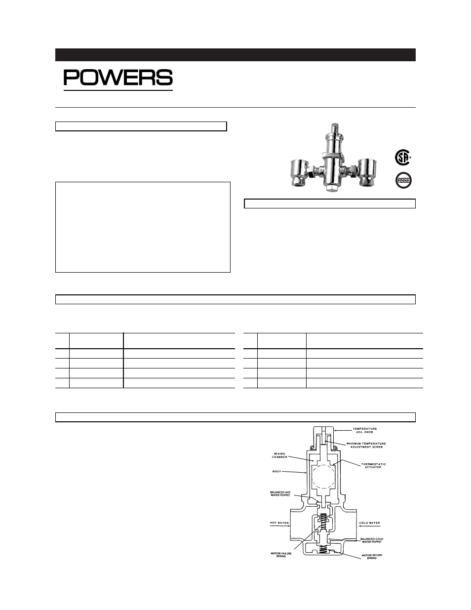
Typical Flow
Hot and cold water supplies enter Hydroguard at indicated ports,
(see Figure 1) then flow past their respective balanced poppet plug
and seats. Next, hot and cold water flow is directed to the mixing
chamber where the thermostatic actuator is located.
Temperature adjustment knob moves the actuator to determine the
discharge temperature.
With a rise in discharge temperature due to pressure or tempera-
ture fluctuation on the inlet, the actuator expands, decreasing flow
of hot water. The reverse occurs with a drop in discharge tempera-
ture.
• Cold water supply failure – causes actuator to expand allowing
the motor to seat hot water poppet.
• Hot water supply pressure failure – causes actuator to contract
allowing return spring to seat cold water poppet.
OPERATION
Figure 1
Form
TI430 v3
OUTLET