Installation, Maintenance – Powers 596 SI Flowrite II Heavy Duty Control Valves User Manual
Page 7
Form TI 596SI v2
Page 7
INSTALLATION
Inspection
Inspect the package for damage. If damaged, notify the appropriate carrier
immediately.
If undamaged, open the package and inspect the device for obvious
damage. Return damaged products.
Requirements
• Pipe wrenches
• Flange gaskets, bolts/nuts
• Installer must be a qualified, experienced technician
CAUTION!
• Install the valve with the flow in the direction of the flow arrow.
• Do not exceed the ratings of the device.
• Avoid locations where excessive moisture, corrosive fumes, or
vibration are present.
Mounting/Orientation
1. The valve should be mounted in a location that is within the
ambient limits of the actuator. When selecting a location, allow
sufficient room for valve linkage, actuator, and other accessories
and for service of the product.
2. The preferred mounting position for the valve is with the valve
stem vertical above the valve body. Avoid mounting the valve so
that the valve stem is below horizontal.
3. On steam applications where the ambient temperature
approaches the limit of the actuator, the valve stem should be
mounted 45° from vertical.
Flanged Connection
The 596SI series flanged valve bodies conform to American Standard 125
Lb. Cast Iron Pipe Flanges. The companion flanges (not provided) should
be the same specification as the valve. The 125 lb. flanges have plain flat
faces and should not be bolted to a raised faced flange.
1.
All parts should be clean to assure the best results.
2.
The pipe with the companion flanges installed should be
properly supported and aligned. Be sure the companion flange is
flush with the face of the valve body flange and lined up
squarely.
3.
Use a gasket material (not provided) that is recommended for
the medium being handled.
CAUTION! Do not apply pipe dope to the valve flange, gasket,
or companion flange.
4.
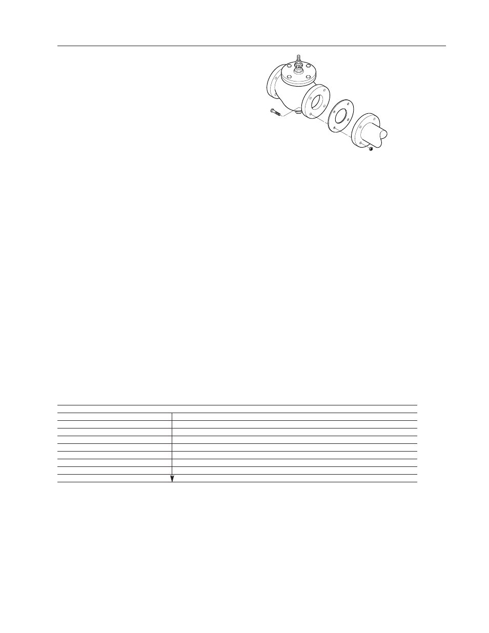
See Figure-5 for flange and flange bolt details.
Figure-6 shows the proper way a flanged valve should be
mounted.
MAINTENANCE
Regular maintenance of the total system is recommended to assure sustained performance. See Table-6 for maintenance kit part numbers.
Table - 6 Maintenance Kits for 596SI Valves
Valve Description
Replacement
Replacement
Valve Repair Kit*
Packing Assembly
Gaskets
2.5 Normally Closed
596 Pack
596250G
SIGOBCTK
3 Normally Closed
596300G
SIHOBCTK
4 Normally Closed
596400G
SIJOBCTK
5 Normally Closed
596500G
SIKOBCTK
6 Normally Closed
596600G
SILOBCTK
2.5 Normally Open
596250G
SIGOBXTK
3 Normally Open
596300G
SIHOBXTK
4 Normally Open
596400G
SIJOBXTK
5 Normally
Open
596500G
SIKOBXTK
6 Normally
Open
596600G
SILOBXTK
* Kit includes replacement packing and stem & plug assembly.
Water System Maintenance
All systems are susceptible to valve and system problems caused by improper
water treatment and system storage procedures. These guidelines are
provided to help avoid valve and water system problems resulting from
improperly treated water or storage procedures and to obtain maximum life
from the valves.
Durability of valve stems and packings is dependent on maintaining non-
damaging water conditions. Inadequate water treatment or filtration can
result in corrosion, scale, and abrasive particle formation. Scale and
particulates can result in stem and packing scratches and can adversely affect
packing life and other parts of the hydronic system.
To maintain non-damaging conditions, follow these guidelines:
• Clean the system prior to start up.
• Use filtration equipment where needed.
• Properly store off-line systems and monitor water treatment results.
• Follow the advice of a water treatment professional.
Valve
Body
Gasket:
Supplied
by Others
Companion
Flange
Figure 6 - Installation of
Flanged End Valves