Valve sizing and selection (water), Cavitation limitations on valve pressure drop – Powers 596 SI Flowrite II Heavy Duty Control Valves User Manual
Page 3
Form TI 596SI v2
Page 3
VALVE SIZING AND SELECTION (WATER)
The sizing of a valve is very important if it is to render good service. If it
is "undersized", it will not have sufficient capacity. If it is "oversized", the
controlled variable may cycle, the trim can be exposed to excessive wear or
wire drawing, and you could expect reduced valve life. To help select the
right valve, it is important to understand your application and its variables
(controlled fluid, temperatures, pressures, min/max load, etc.). When
your system variables are known and you have calculated actual demand, it
is possible to select the right Powers valve for your application. The
following technical data should help you in selecting a valve for your water
control applications. For fluid applications other than water, contact
Powers’ application engineering.
On/Off Control:
These types of applications are normally line sized to reduce pressure drop
and pump size. In these applications it is important to verify valve seat
leakage will not result in system overheat or damage. If this is a concern, it
is necessary to take precautions to alleviate this potential problem.
Proportional Control:
In applications where the close-off pressure at the valve is below 20psig,
use a pressure drop of 5psi.
In applications where the close-off pressure at the valve is above 20psig, it
is generally recommended to take 25-50% of the system pressure drop at
the control valve to maintain good valve/system performance. Certain
applications can successfully utilize lower pressure drops across the valve
(5-25%) if system fluctuations are kept to a minimum. If not, the valve is
considered oversized it will not effectively throttle until it is nearly closed
thereby resulting in poor control.
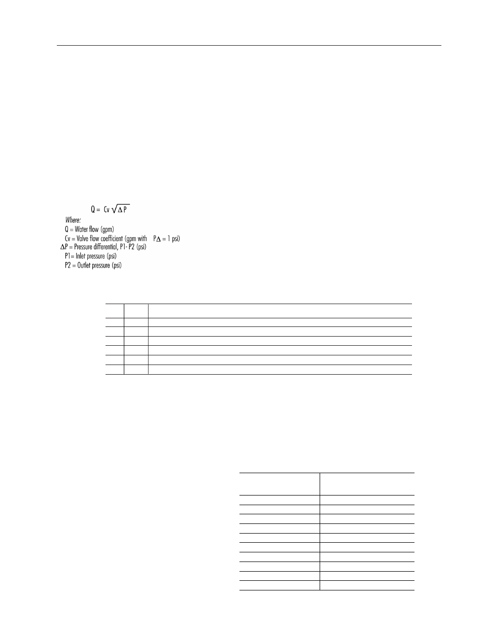
Refer to the following table for flow….
Table - 1
Water Capacity in Gallons Per Minute
Valve Cv
Size
Rating
Differential Pressure (
∆
P in psi)
5
10
20
30
40
50
60
70
80
90
100
125
2.5
65
145
206
291
356
411
460
503
544
581
617
650
727
3
85
190
269
380
466
538
601
658
711
760
806
850
950
4
145
324
459
648
794
917
1025
1123
1213
1297
1376
1450
1621
5
235
525
743
1051
1287
1486
1662
1820
1966
2102
2229
2350
2627
6
350
783
1107
1565
1917
2214
2475
2711
2928
3130
3320
3500
3913
CAVITATION LIMITATIONS ON VALVE PRESSURE DROP
A concern in high temperature water systems is the potential for cavitation/flashing, which is caused by the downstream pressure being lower than that of the
vapor pressure of the fluid. This basically causes the water to "boil" and can result in reduced flow/capacity, excessive noise, vibration, wear and should be
avoided if possible. Use the following equation to estimate the maximum allowable pressure drop across the valve:
Pmax = 0.5 (P1 – Pv)
Where:
Pmax = Maximum allowable pressure drop
P1 = Absolute inlet pressure (psia)
Pv = Absolute vapor pressure (refer to psia - Table 2)
Absolute pressure = gage pressure + 14.7
Table-2
Vapor Pressure of Water Table
Water Vapor
Water Vapor
Temp.
Pressure
Temp.
Pressure
(°F)
(psia)
(°F)
(psia)
40
0.12
140
2.89
50
0.18
150
3.72
60
0.26
160
4.74
70
0.36
170
5.99
80
0.51
180
7.51
90
0.70
190
9.34
100
0.95
200
11.53
110
1.28
210
14.12
120
1.69
220
17.19
130
2.22
230
20.78