Repair kits (repair kit parts), Maintenance and troubleshooting, Installation instructions – Powers 1430 Series HiLo Master Mixing Valve User Manual
Page 3
TI 1430 HiLo
Page 3
PART DESCRIPTION
REPAIR KIT INCLUDES:
1432
1434
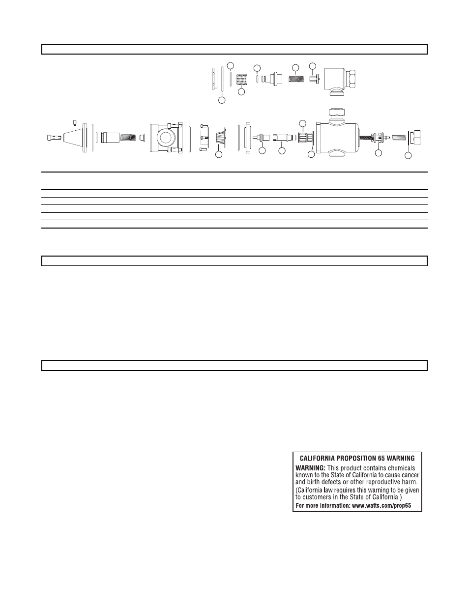
(Numbers below correspond with numbers in Figure 2)
HiLo Motor Replacement Kit
1, 2 and 13 Gaskets, and “O” Rings
390-500
390-543
Strainer Replacement
7, 8, 9, and 10
230-134
230-136
Checkstop Replacement
7, 8, 10, 11, and 12
230-135
230-137
Gasket and Disc Replacement
1, 2A, 4, 6, 7, 8, 10, and 12
390-298
390-306
Mixing Valve Replacement
3, 4, 5, and 6
390-068
390-070
Strainer and Checkstop Repair Kits contain parts for one (1) pair. Repair kits include parts for both old-and new- style checkstop (Items 7, 8, 10, 12) and body Cap Gasket (Item 6). Use appropriate part for your style Hydroguard. If replacing either
bonnet or stem on old-style checks, you must replace both with new parts. Do not use the new bonnet with an old stem or vice versa. Repair Kits containing “O” Rings include silicone gel for use on “O” Rings during installation.
7
8
9
10
11
12
13
2
1
4
3
5
6
"O" RING
GASKET
SCREEN
"O" RING
SPRING
POPPET ASSEMBLY
EXPANDABLE
RESTRICTOR
THERMAL
ACTUATOR
MOTOR
ADAPTER
HOT WATER
POPPET
"O" RING
COLD WATER
POPPET
"O" RING
REPAIR KITS (Repair Kit Parts)
What to look for if:
• The flow of water is less than desired...
a. Stop valves or supply to Hydroguard not fully open.
b. Clogged checkstop strainer screens.
c. Accumulation of lime deposits around valve seats.
d. Low supply pressures or unusual supply temperatures.
• The flow of water is completely shut off...
a. Stop valves or supply valves are completely closed.
b. Valves downstream from Hydroguard fully closed.
c. Loss of either hot or cold water supply pressure.
• Discharge temperature varies...
a. Very large restriction in outlet flow.
b. Very large drop in inlet pressure.
c. Very large fluctuation of hot water supply temperature.
d. Worn valve seats.
e. Minimum flow requirement not achieved.
f. Lime deposits around motor, poppets and/or seat.
MAINTENANCE AND TROUBLESHOOTING
1. IMPORTANT: Flush all piping thoroughly before installing.
2. Valves are to be installed as close to building inlet supply
as possible to prevent/minimize pressure fluctuations.
3. Remove body screws to turn outlet to any of four positions.
The Hydroguard body can be rotated to any position due
to the union inlets. Note: Make certain the body screws
and unions are tightened securely to prevent leakage.
4. CAUTION: When the Hydroguard supplies tempered water
to self-closing and/or solenoid valves, provide a shock
absorber (Powers Part No. 460-353) on the discharge line.
This protects the Hydroguard thermostatic motor from
damage by water shock waves generated by the quick
closing valves.
5. Before use, check maximum discharge temperature.
Reset if necessary.
OPERATION CHECK:
After Hydroguard is installed, make certain the supply stop
valves and strainers are free and clean and ready for operation
by disassembling checkstops as shown in "Servicing", steps
1, 2, and 3.
INSTALLATION INSTRUCTIONS
Figure 2