Prior to installation, Set up procedure, Continuous recirculation – Powers PowerStation XP Single and Multi-Valve Series - Triple Valve 1 - 416 gpm User Manual
Page 2: Aquastat
NOTE: Perform all 15 steps before moving on to the next section.
Steps 1-15 are to set temperature of thermostatic valves and
to set differential across the PRV
1. Make sure all ball valves are open and leave pump off.
2. Open up enough fixtures to flow a minimum of 15 gpm.
3. Before continuing on to the next step, make sure the read-
ings on inlet gauges T/P2 and T/P3 are steady.
4. Close the ball valve B6 and B7.
5. Adjust the temperature of mixing valve #3.
Refer to IS-P-MM430
6. Open the ball valve B7, and close the ball valve B8
7. Adjust the temperature of mixing valve #2. Refer to IS-P-
MM430.
8. Set the PRV as follows for a 15psi differential
a) Loosen the locknut at the top of the PRV. This must be all
the way out or you will be limiting the range of adjustment.
b) Adjust the PRV so the outlet pressure gauge (top) reads
15psi less than the supply pressure gauge (bottom). Turning
the adjustment screw counterclockwise will increase the
differential across the PRV (allowing the PRV to open later).
After adjusting locknut turn fully clockwise.
9. Close the ball valve B7 and open the ball valve B6.
10. Adjust the temperature of mixing valve #1.
Refer to IS-P-SH1430.
11. Open the ball valves at the discharge of all three valves B6,
B7 and B8 .
12. Open more fixtures to increase the total flow through valve
system and verify outlet temperature is holding steady at set
point, watch gauge T/P1.
13. Begin to close fixtures, leave enough open to have a flow of
2 gpm and verify outlet temperature is holding steady at set
point, watch gauge T/P1.
14. Once valve system is operating properly, close all fixtures.
15. Skip to the type of recirculation you will be using below.
1. Flush all piping thoroughly before installing.
2. Check for leaks.
Prior to Installation
n
Set Up Procedure
n
Use of a Circuit Setter to balance a closed loop.
1. Apply power to pump P1
2. Open C1 approximately 10%.
3. Allow time for recirculated water to travel around the loop.
4. If the temperature at gauge T/P4 begins falling too far below
the set point of the mixing valve, you will need to open C1
another 10% and allow more water to return to the water
heater.
5. If the temperature at gauge T/P4 begins to rise, you will need
to close C1 5% and allow more water to flow in the cold inlet
of mixing valve.
6. Repeat steps 4 and 5 until the temperature at T/P4 is stable
(less than the set point of the mixing valve).
7. The system is now set.
NOTE: For any problem, refer to Troubleshooting section of the
document or contact Powers' Technical Support Department at
1.800.669.5430 or [email protected].
Continuous Recirculation
n
Adjust Aquastat with all fixtures downstream of the mixing
valve closed.
1. Apply power to pump P1.
2. Set the Aquastat high set point temperature. As a recom-
mendation, start with the high set point 5°F degrees below the
mixing valve set point.
3. With the recirculation loop temperature at its maximum, the
pump will remain off until the loop temperature drops below
the high set point.
4. Wait until the recirculation line cools down, and verify the
pump turns on at this point.
5. Verify recirculation line heats back up and turns pump off at
the maximum setting from step 2.
6. The system is now set.
Aquastat
n
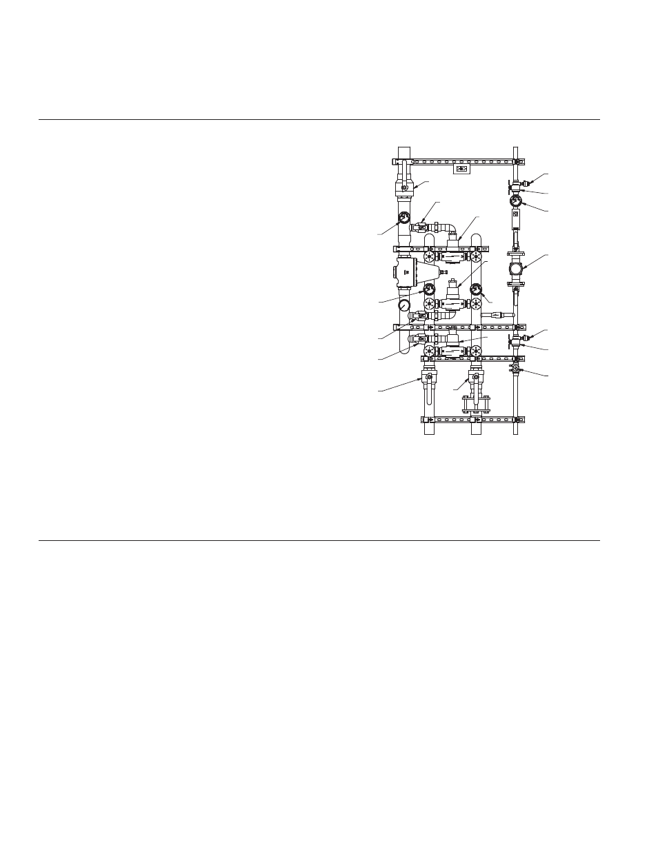
1434TV and LF1434TV
B1
B2
B8
B7
T/P 2
T/P 1
B4
B6
#1
#2
T/P 3
#3
D1
B5
T/P 4
P1
D2
B3
C1
D1
B5
T/P 4
T/P 2
T/P 1
T/P 3
P1
D2
#3
#2
#1
B3
C1
B2
B1
B8
B6
B4
B7
2