Configuration instructions, Notice – Powers 460 Series AquaSentry 2 Temperature Alarm System User Manual
Page 3
3
1
2
3
4
5
6
7
8
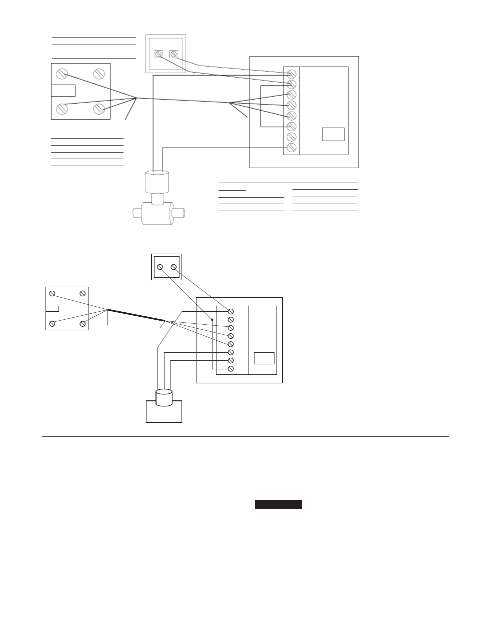
Solenoid (Optional)
Jumper terminals 2 and 6
Connect solenoid to terminals 1 and 8
Sensor Junction Box
Red
Sensor power—Red wire
Yellow Sensor signal—Yellow wire
Black
Sensor return—Black wire
Green
N–C
Module Connections
1
24 VAC
To Transformer
2
24 VAC
3
Sensor return—Black wire
4
Sensor signal—Yellow wire
}
Black
Red
Yellow
Yellow
Black
Red
Transformer
2 wires
Connect to 117 VAC
2 screw terminals
Connect to module
terminals 1 and 2
5
Sensor power—Red wire
6
Relay normally closed
7
Relay normally open
8
Relay common
Figure 3—Wiring for
Gree
n
N/C
Gr
ee
n
N/
C
Dip
Switch
solenoid valve
(solenoid valve supplied
by others)
1. Apply power to the panel. The correct process temperature
should be displayed on the display. If the alarm is sounding,
press the “RESET” key once.
2. Ensure dip switch #2 on the circuit board is in the off position.
(This switch “locks out” the “SET” key if activated.)
3. Press the “SET” key twice to display “HSP” (high setpoint)
value. Use the up or down arrow keys to set the upper setpoint.
4. Press the “SET” key twice to display “LSP” (low setpoint)
value. Use the up or down arrow keys to set the lower setpoint.
If no low alarm is used, set the lower setpoint for 32–35°. (This
will ensure that the alarm will sound if the probe is damaged or
disconnected.)
5. Press the “SET” key three (3) times to return to the operating
mode. Press the “RESET” key if the display is flashing. Unit
should now be fully functional.
6. Position dip switch #2 on the circuit board on the “on” position
to prevent unauthorized configuration changes.
If there is a difference between the reading on the display and the
actual process temperature, note the number of degrees the read-
ing is off. Press the “SET” key 6 times, then enter the different tem-
perature in the CAL setting with the up and down arrow key. Press
the “SET” key one more time to return to the operate mode.
Configuration Instructions
n
NOTICE
1 AC
2 AC
3 GND
4 SEN
5 +5V
6 NC
7 NO
8 COM
BLACK
RED
YELLOW
YELLOW
BLACK
RED
GREEN
N/C
GREEN
N/C
TRANSFORMER
DIP
SWITCH
Figure 4 - Wiring for
Motorized Valve
(Motorized Valve order
separately)