Powers 460 Series AquaSentry 2 Temperature Alarm System User Manual
Lead free, Technical instructions
The Series LF460 Aqua Sentry 2 Alarm System monitors for
high or low temperature conditions. The system utilizes an
accurate solid state temperature sensor and microprocessor
based digital circuitry to sense and report abnormal tempera-
ture conditions. Standard sensing range is –40°F to 199°F or
–40°C to 93°C (switchable). The alarm panel can be mounted
remotely and provides both audible and visual indication of
alarm condition. With the addition of a solenoid, the alarm can
function as an emergency shutdown system.
A unique latching circuit is used so that the alarm holds
despite a return to normal condition. This feature indicates that
a dangerous condition did exist. The alarm can be silenced
at any time by pressing the reset key. After the temperature
returns to normal, the system can be reset by pressing the
reset key twice. The system cannot be reset while the tem-
perature is outside the setpoints. The alarm module can be
panel mounted, or installed in a standard 4 x 4 electrical wall
box (supplied).
Use of the Series LF460 Aqua Sentry II Alarm System, along
with a electrically actuated valve, helps assure requirements
are met to maintain delivery temperature below (or above) a
certain temperature. (Typical of domestic water systems in
health care and nursing facilities).
Description
n
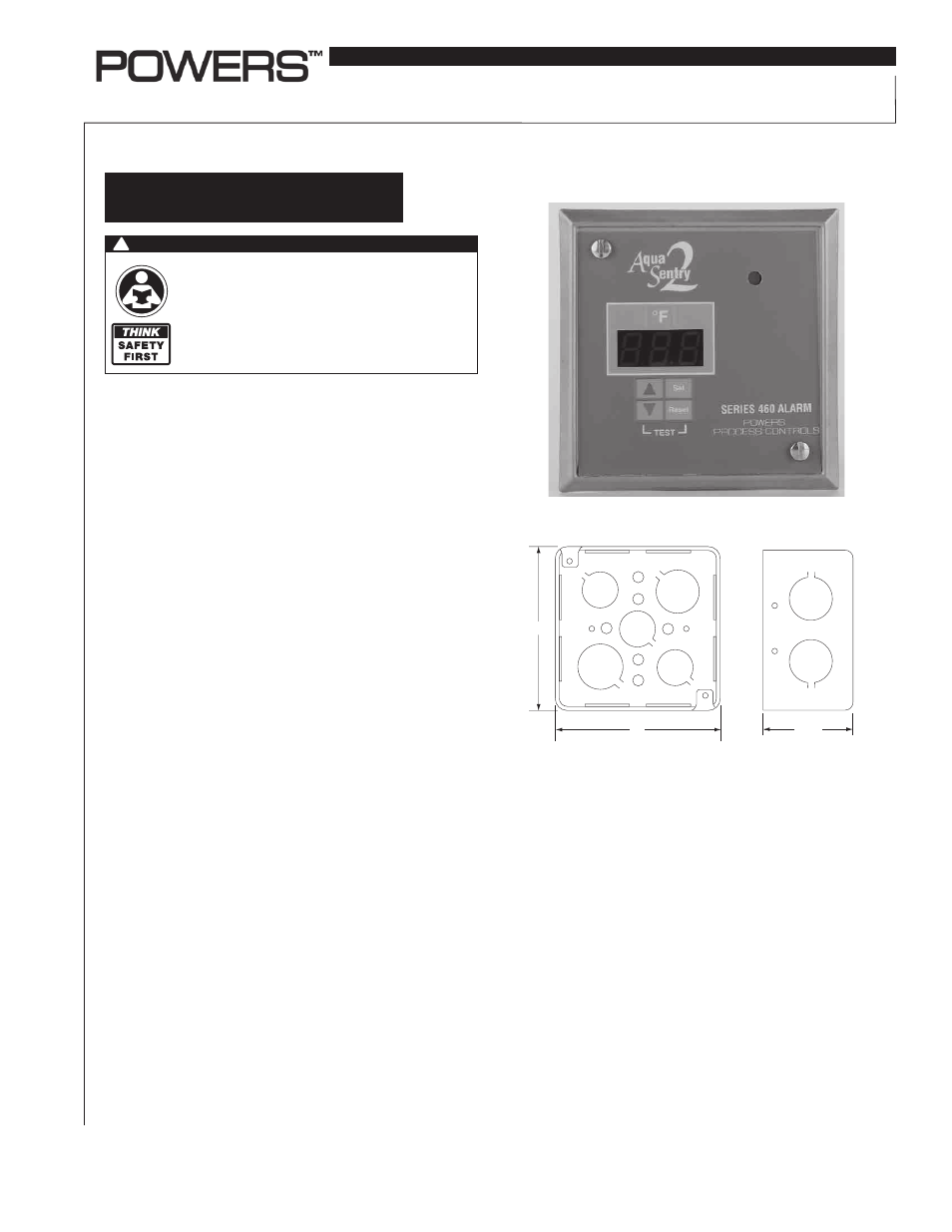
SERIES LF460 ALARM, MODEL LF4600150
Temperature Alarm System
Technical Instructions
IS-P-MV460AS
I. Standard Operation of the Series LF460 Alarm
connected as shown in Figure 3 on page (3):
A. Display will read current temperature with sensor connected
and system in “safe” condition.
B. If sensor is improperly connected or if the sensor is properly
connected and there is an increase in the water temperature
above or below the setpoints of the thermostat:
1. Audio alarm will sound.
2. Display will flash.
3. Current temperature will be displayed.
4. Valve will close.
If condition 1-B occurs, press RESET key twice.
A. If the sensor is properly connected and a dangerous condi-
tion exists, the circumstances described in I-B (2, 3, 4) will
persist.
B. If the sensor is improperly connected, the circumstances
described in I-B (2, 4) will persist.
C. If the sensor is connected properly, and the system is in a
safe condition:
1. Alarm will be silent.
2. Display will be on.
3. Current temperature will be displayed.
4. Valve will open.
II. To test the Series 460 alarm, press the keys marked
▼
and “RESET” simultaneously.
A. Audio alarm should sound.
B. Display will flash.
C. Valve will close.
To terminate the audio alarm, press the “RESET” key and
release.
A. Audio alarm will turn off.
B. Display will continue to flash.
C. Valve will remain closed.
To terminate test condition, press “RESET” key again.
A. Display will stop flashing.
B. Temperature will be displayed.
C. Valve will open.
Mode of Operation
n
4ʺ
2-3/16ʺ
4ʺ
K
Note: Position of mounting holes on utility box must match up with the
holes on Series 460 alarm front panel.
(Front)
(Right Side)
Figure 1—Dimensional Data
WARNING
!
Read this Manual BEFORE using this equipment.
Failure to read and follow all safety and use infor-
mation can result in death, serious personal injury,
property damage, or damage to the equipment.
Keep this Manual for future reference.
LEAD FREE
*
*The wetted surface of this product contacted by consumable
water contains less than 0.25% of lead by weight.