Powers ETV400 Emergency Tempering Valves with Internal Cold Water Bypass User Manual
Page 3
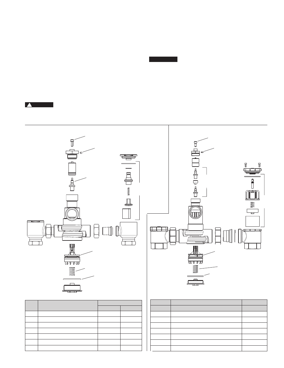
Index
Description
Part No.
ETV200
ETV400
1
Temperature Adjustment Screw
390 777
390 787
2
Adjustment Locking Screw
390 795
390 795
3
Actuator
390 808
390 810
4
Plunger Kit
390 802
390 803
5
Spring
390 620
390 162
6
O-Ring
1101575
2101003
7
Checkstop Rebuild Kit
390 800
390 801
ETV500
Index
Description
Part No.
1
Temperature Adjustment Screw
390 787
2
Adjustment Locking Screw
390 795
3
Actuator Kit
390 815
4
Plunger Kit
390 816
5
Spring
390 162
6
O-Ring
2101003
7
Checkstop Rebuild Kit
390 811
3
Disassembly
1. Close supply valves and/or checkstops
2. Remove valve from its outlet piping. Work should be performed on a
clean table or workbench.
3. To remove thermal actuator from top
a) Loosen adjustment locking setscrew.
b) Remove bonnet and overload assembly.
c) Lift out thermal actuator.
d) Assemble in reverse order
4. To remove the plunger assembly from bottom
a) Remove the bottom cap.
Spring is under tension.
b) Pull out spring
c) Pull out plunger using a pair of pliers.
d) Reassemble in reverse order.
After reassembling go back to thermal actuator section and make sure it
is sitting in its holder properly.
Inspection
1. Inspect body for any damage, deposits or pitting. Clean or replace as
necessary.
2. Check the actuator for proper operation at room temperature. Hold
actuator between your finger and thumb. Apply force on end of stem.
Measure the entire length of the actuator and then place it in the hot
water (105-110°F) for 10 seconds. Actuator stem should extend at
least 1/8" longer than when at room temperature.
Due to the safety nature of this product, we recommend
removal of the valve by a licensed contractor and full
inspection of all components whenever the valve is disas-
sembled for any reason. Temperature must be checked and
adjusted. For temperature adjustment see Adjustment &
Testing section.
Disassembly and Inspection
n
2
3
4
4
5
5
6
6
7
7
3
ETV 200
ETV 400
ETV 500
Parts List
n
1
1
2
NOTICE
CAUTION
!